Table of Contents
What is an electric circuit?
When we turn off light always think about how to travel the electricity from switch to bulb. in our 9th standard, we got to know what is an electric circuit but somewhere we have some confusion on the same topic.

Introduction
It is the 1st step to know about the basic electronics and start of any branch in the electronic and electrical.” The close path in which the electric current flows it can consist of the resistor, capacitor, and other electronic and electrical components”. this is the definition of “what is an electric circuit”.
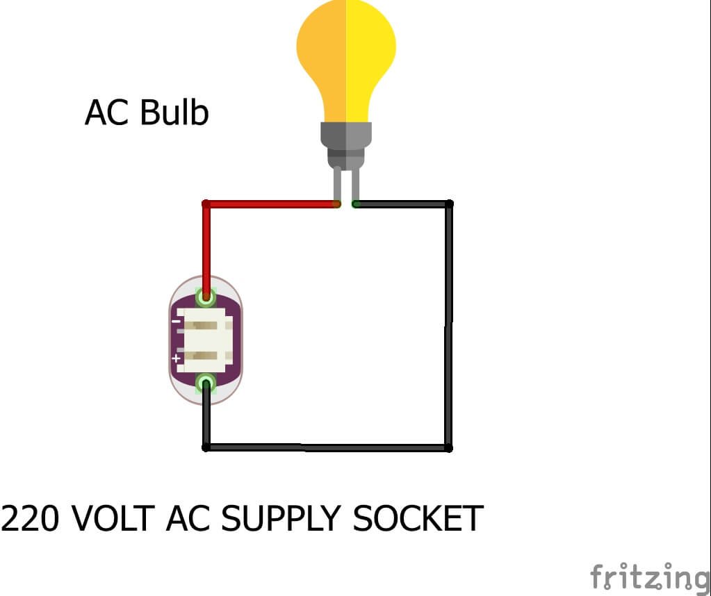
an open path can’t be a circuit. to make a circuit path should be closed. So, that the electricity can travel from one point to another point.
| Led | Resistor | 5 Volt Battery |
| Anode terminal | Terminal 1 | |
| Terminal 2 | Positive terminal | |
| Cathode terminal | Negative terminal |
| AC Bulb | 220 Volt AC Supply |
| Terminal | Phase terminal |
| Terminal | Neutral terminal |
example of the circuit:- a light bulb in your room connects to the electricity and when you switch it on the circuit is completed. and when the circuit is completed the current can flow in the circuit.
Current always flows from the positive to the negative direction in a circuit.
To turn on the light bulb electric current necessary to complete the whole path. the current starts fro from one point and ends at another point. We are starting basic electronics too. this is the first post that’s why we are posting about the circuit and then we will discuss the current, voltage, and resistor all the topics we will cover soon. I believe now you understand what is an electric circuit
Types of electrical circuit
So, here we are going to describe how many types of circuits.
AC circuit!
Do you think there is something different in AC and DC Circuits? The only difference is the power rating the components used in the AC circuit required more power. AC circuit may bigger or longer than the DC circuit. Because there is no ground and VCC. but here the current flow from phase to neutral.
DC Circuit!
Dc means Direct current. There are no ups and downs in the current. it is uniform if I have 5v amplitude of voltage then it will remain the same it will be not going to the 0 and in negative. in DC circuits there are small components with low power used than AC. no doubt it is more harmful than AC but you can’t feel it if the voltage amplitude is less. Circuits used in mobile phones are DC circuits.
Series and Parallel Circuits
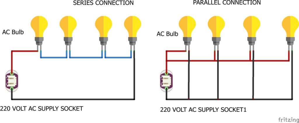
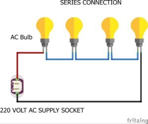
Series Connection Table for AC Circuit
| Bulb 1 | Bulb 2 | Bulb 3 | Bulb 4 | 220 Volt AC |
| Terminal 1 | Terminal 2 | Terminal 1 | Terminal 2 | Phase |
| Terminal 2 | Terminal 1 | Terminal 2 | Terminal 1 | Neutral |
Parallel Connection Table for AC Circuit
| Bulb 1 | Bulb 2 | Bulb 3 | Bulb 4 | 220 Volt AC |
| Terminal 1 | Terminal 1 | Terminal 1 | Terminal 1 | Phase |
| Terminal 2 | Terminal 2 | Terminal 2 | Terminal 2 | Neutral |
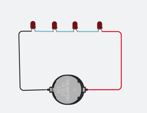
Series Connection table for DC Circut
| Led 1 | led 2 | led 3 | DC Battery |
| Anode | Cathode | Anode | Negative |
| Cathode | Anode | Cathode | Positive |
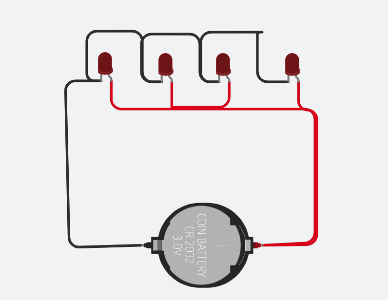
Parallel Connection table for DC Circut
| Led 1 | led 2 | led 3 | DC Battery |
| Cathode | Cathode | Cathode | Negative |
| Anode | Anode | Anode | Positive |
In-circuit the current flow due to the presence of voltage. voltage is like pressure which forces the charge to flow from one end to another end.
There are two types of Circuits,
Series Circuits
In a Series circuit, all the components are connected in Series or serially. or we can say it one to another. there are two terminals in any device so one terminal is connected to the previous device and another terminal is connected to the next device. for example, there are 10 students in a line and tell them to turn right and touch his left hand with the left person and right with the right person. this is a series circuit. in series circuit current flow in one path.
parallel Circuits
In a parallel circuit, all the components are connected in parallel. or we can say it one by one. there are two terminals in any device so one terminal is connected to the power source ist terminal and another terminal is connected to the power source another terminal. you can more understand by the given image.

Now we should talk about one more circuit which is an Integrated circuit this is out of topic in this post but there is confusion in many minds so we would clear this too. An integrated circuit is known as IC which consist of more than 2-3 transistor or we can say multiple transistors on a single chip. It is used in almost every electronic project. it is not related to the basic circuits. so ignore it right now. all the best I hope you will learn a lot in this post. if you have any query you can ask us in the comment box.