
hey guys , welcome back to the techatronic. In this tutorial we are going to make a water level alarm project which consist display buzzer and led. the project is beginner level project but it is useful. you can use this project in your home. mainly we create this project for learning purpose. there you will learn many things like coding, electronics and robotics.
we are making full tutorial on how to make this project workiing with code ,circuit and explanation. if you want to learn how to make you need to read full article. we are using 3 LED’s here which is inside the learner kit which we provide.
Introduction to Water Level alarm project with Buzzer
Water management has become a critical concern in today’s world, whether it is for homes, industries, or agricultural use. One common problem faced by many households is water overflow from tanks due to negligence or the absence of a proper monitoring system. A Water Level Alarm using Arduino and OLED display offers a smart, reliable, and cost-effective solution to this issue by providing real-time information about water levels and alerting users before overflow or dry conditions occur.
In this project, an Arduino microcontroller acts as the brain of the system, continuously reading data from water level sensors placed at different heights inside the tank. Based on the detected water level, the system triggers an alarm and displays clear status messages on an OLED display, such as “Low Level,” “Medium Level,” or “Tank Full.” The use of an OLED screen enhances user experience by presenting sharp, easy-to-read visual feedback, even in low-light conditions.
This Arduino-based water level alarm is not only useful for domestic water tanks but also finds applications in overhead tanks, underground reservoirs, laboratories, and industrial water storage systems. It helps prevent water wastage, protects water pumps from dry running, and reduces the need for constant manual monitoring. Moreover, the project is beginner-friendly and ideal for students, hobbyists, and electronics enthusiasts who want hands-on experience with embedded systems, sensors, and display modules.
Through this article, you will gain a clear understanding of how a water level alarm works, the components required, circuit connections, and the Arduino code involved. By the end, you will be able to build a practical and efficient water level monitoring system that combines automation, safety, and smart technology.
Working of Water Level alarm project
The working of this project is very easy. We are using a water level sensor here, which is dipped in the tank. The sensor is connected to the Arduino via A0 pin and is sending continuous data to the Arduino. the Data is between 0 to 1024. if the water level is low or no water it will show the 0 and as the level rises, the counting start increasing.
or the value of the sensor increasing and arduino getting this data from the sensor. now we put the conditions with this data. like we are using 3 different LED’s in this project we will set 3 different condition with 3 different threshold. like if the value is less than 300 then the green LED will glow. if the value is between 301 && 600 then yellow LED will turn on. and if the value is more than 601 then the red LED will turn on.
so, when the level of water rises then the led will indicate with different LED’s and buzzer.
Now, we will start making this project. So, first we will need the Component List first. \
Required Components for Water Level alarm project
- Arduino nano
- Arduino Nano Shield
- Arduino Cable
- 3 LED Module
- Buzzer Module
- Breadboard
- Jumper Wire
- OLED Display
- Water Level Sensor
Here we have given all the component details. Now we need to assemble all the components, which require a circuit Diagram
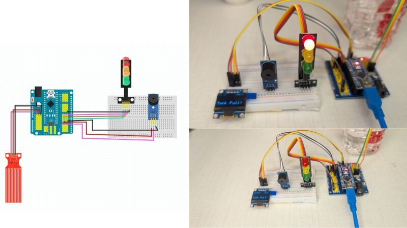
Circuit Diagram for Water Level alarm project

Overview of the Circuit
This circuit consists of:
- Arduino (with sensor shield)
- Water Level Sensor
- 3-LED Traffic Signal Module (Green, Yellow, Red)
- Buzzer Module
- Breadboard + Jumper Wires
The Arduino acts as the brain, reading the water level and controlling LEDs + buzzer.
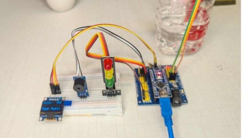
1️⃣ Water Level Sensor Connections (Left Side – Red Sensor)
The water level sensor has 3 pins:
| Sensor Pin | Connected To | Purpose |
|---|---|---|
| S (Signal) | Arduino A0 | Sends water level value |
| + (VCC) | Arduino 5V | Power supply |
| – (GND) | Arduino GND | Ground reference |
📌 How it works:
As water touches more sensor tracks, the resistance changes and Arduino reads a higher analog value on A0.
2️⃣ Arduino Power Distribution
From the Arduino:
- 5V pin → Breadboard positive rail
- GND pin → Breadboard ground rail
These rails are used to power:
- LED module
- Buzzer module
✔ This keeps all components at a common ground, which is very important.
3️⃣ Traffic Light (3-LED) Module Connections (Top Right)
This module has 5 pins (3 LEDs + VCC + GND).
| LED Module Pin | Connected To Arduino | Function |
|---|---|---|
| GND | GND | Common ground |
| VCC | 5V | Power |
| Green LED | Digital Pin 5 | Low water level |
| Yellow LED | Digital Pin 6 | Medium level (warning) |
| Red LED | Digital Pin 7 | Tank full |
📌 Logic:
- Green ON → Water low
- Yellow BLINK → Water medium
- Red ON → Tank full
(The Arduino controls each LED individually.)
4️⃣ Buzzer Module Connections (Right Side – Blue Module)
The buzzer module has 3 pins:
| Buzzer Pin | Connected To | Purpose |
|---|---|---|
| SIG | Arduino D4 | Sound control |
| VCC | Arduino 5V | Power |
| GND | Arduino GND | Ground |
📌 How it works:
- Arduino sends
tone()signal to D4 - Different frequencies create different alarm sounds
5️⃣ Breadboard Wiring Role
The breadboard is used to:
- Distribute 5V and GND
- Mount the LED module and buzzer
- Avoid direct Arduino pin congestion
✔ All grounds are common
✔ All power lines come from Arduino
6️⃣ Complete Signal Flow (Simple Words)
- Water touches sensor
- Sensor sends analog value to A0
- Arduino checks value in code
- Arduino:
- Turns ON/OFF LEDs (D5, D6, D7)
- Controls buzzer sound (D4)
- Visual + sound alert is generated
After Completing The Circuit, we need a Code which can work for our system. To write the code we need Arduino IDE software.
Water Level Alarm Project with Buzzer Arduino Code
#include <Wire.h>
#include <Adafruit_GFX.h>
#include <Adafruit_SSD1306.h>

#define SCREEN_WIDTH 128
#define SCREEN_HEIGHT 64

Adafruit_SSD1306 display(SCREEN_WIDTH, SCREEN_HEIGHT, &Wire, -1);

// Pin definitions
#define waterSensor A0
#define greenLED 5
#define yellowLED 6
#define redLED 7
#define buzzer 4

int waterValue = 0;

void setup() {
  pinMode(greenLED, OUTPUT);
  pinMode(yellowLED, OUTPUT);
  pinMode(redLED, OUTPUT);
  pinMode(buzzer, OUTPUT);

  Serial.begin(9600);

  if (!display.begin(SSD1306_SWITCHCAPVCC, 0x3C)) {
    while (true);
  }

  display.clearDisplay();
  display.setTextColor(WHITE);
}

void loop() {
  waterValue = analogRead(waterSensor);
  Serial.println(waterValue);

  // 🔴 IMPORTANT: Stop buzzer first
  noTone(buzzer);

  display.clearDisplay();
  display.setTextSize(1);
  display.setCursor(0, 0);
  display.print("Water: ");
  display.println(waterValue);

  // ---------------- VERY LOW LEVEL ----------------
  if (waterValue < 720) {
    digitalWrite(greenLED, HIGH);
    digitalWrite(yellowLED, LOW);
    digitalWrite(redLED, LOW);
    // ✅ No buzzer here

    display.setCursor(0, 40);
    display.println("Level: LOW");
  }

  // ---------------- MEDIUM LEVEL ----------------
  else if (waterValue >= 720 && waterValue < 745) {
    digitalWrite(greenLED, LOW);
    digitalWrite(redLED, LOW);

    digitalWrite(yellowLED, HIGH);
    tone(buzzer, 1000);   // Beeping warning

    delay(250);
    digitalWrite(yellowLED, LOW);
    noTone(buzzer);
    delay(250);

    display.setCursor(0, 40);
    display.println("Level: MEDIUM");
  }

  // ---------------- FULL LEVEL ----------------
  else {
    digitalWrite(greenLED, LOW);
    digitalWrite(yellowLED, LOW);
    digitalWrite(redLED, HIGH);

    tone(buzzer, 2000);   // Continuous alarm

    display.setCursor(0, 40);
    display.println("Tank Full!");
  }

  display.display();
}
Now you have Circuit and Code both, you need to upload the code into the Arduino and enjoy the Project.