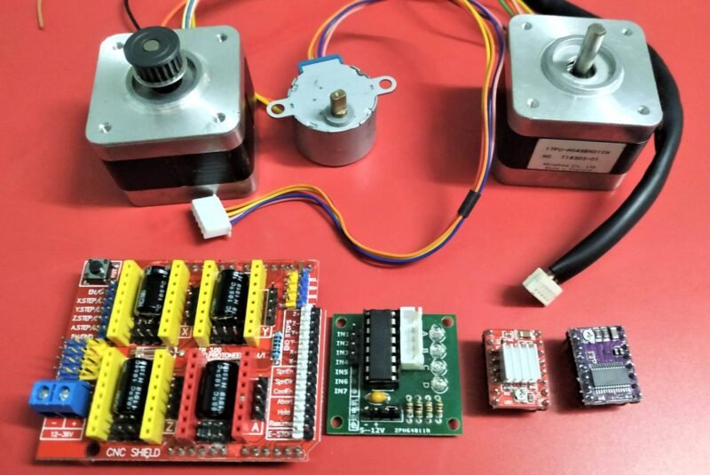
Hey There, I’m back with another interesting article on basic electronics. Today we’re going to discuss all types of stepper motors that I have used. so, everyone here wants to know what is the stepper motors. so, here we are going to make a full details article on the stepper motor, types of stepper motors, working if stepper motors and more.
- Stepper Motors are basically motors with some special functionality, construction, working, and cases. Unlike common brushed motors, these motors do not work in the same manner.
- There are many types, shapes & sizes of stepper motors available in the market ideal for different uses but the choice and usage vary according to your use and need.
- Power to these stepper motors varies according to the shape and size that is clearly mentioned in their datasheet, So make sure to read them before connecting them

What are Stepper Motors?
- Steppers Motors are also types of motors that are not meant for common purposes like the Brushed DC motors, as they require special drivers and controllers to make them run.
- Stepper motors have some complex construction unlike other motors, but the working is the same. As their construction is different, they may be a bit hard to drive and understand.
- These work on the number of steps, direction, and steps per revolution, these terms seem to be a bit confusing but are very simple as explained further.
- They also work on the principle that a current-carrying coil experienced a force when kept in a constant magnetic field. But there is a subtle difference as in this rotating part is the permanent part while the stationary part is the electromagnetic coil.
- The connection points of stepper motors may vary from model to model, but the only difference will be in the number of stators or coils in the stepper motor.
- There are special drivers that are meant for this purpose, so to drive these motors these drivers usually need steps and direction information for making the motor rotate.
- We need always a command to rotate the stepper motor which can be fulfilled by a simple controller like Arduino with a stepper motor.
Construction
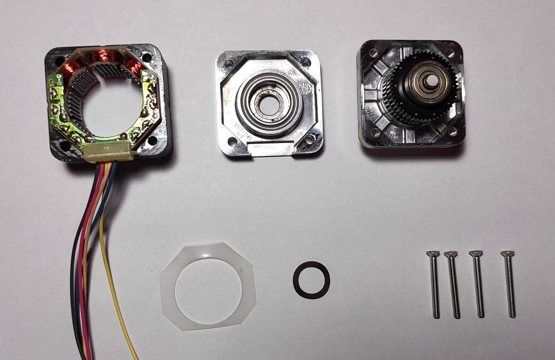

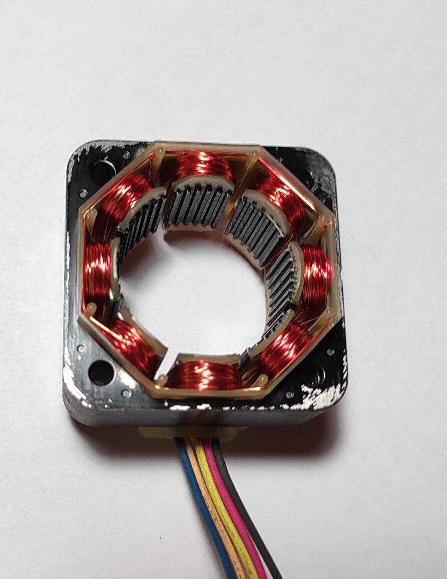
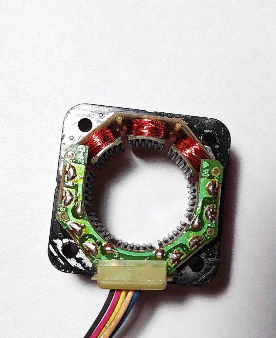

- The construction of these stepper motors is a bit complex but easy when understandable as like their working. The images attached above are the actual images clicked by dismantling a stepper motor (NEMA 17).
- It consists of pairs of stators, which are actually coiled and responsible for creating an electromagnetic field and rotating the rotor part of the nema 17 stepper motor.
- The stator is a part that rotates in the electromagnetic field. It has grooved teeth magnetic cylindrical core fixed in the center of a thin rod, which response to the electromagnetic field created by stators and hence rotates.
- The ends of the rotor are also attached to the ball bearing to make the movement easier and smooth. Also, a metal washer is attached to the bottom part to reduce the wear and tear of the bottom ball bearing.
- Also, the front ends of each stator are attached with some metal strips to enhance the electromagnetic field created by the stator coils, which are also grooved in order to match that of the rotor grooves.
- The wires also solders to the Coils of the stator either directly or with the help of PCB as in my case. These are soldiers in pairs as I said, the opposite of each of the stators are solder similarly to create an even parallel magnetic field.
Working
- The working of the stepper motors is quite simple to understand, as these are somewhat similar to that of the brushless motors. In a brushless motor, the current is supplied to the motor with 3 wires with a phase difference between them that determines its speed.
- Similarly, in the case of the stepper motors, each pair of stators gets activated to make the magnetic rotor part move.
- The grooves in both the magnetic core rotor and a pair of stator coils try to match themselves to the magnetic field, hence making movement from the original position to the stationary magnetic field position.
- Then the next or the adjacent pair of the stator gets activated in the same manner as that of the previous one, but it depends on the direction in which you want the motor to move in.
- The magnetic rotor then again moves from the previous position to the stationary magnetic field position, hence making a rotation movement or the step.
- The total number of steps required to make one complete rotation is called steps per revolution of that stepper. It can easily find out by dividing 360° by the number of steps required to make one complete revolution.
UniPolar
- In the unipolar configuration, only a single pair of the coil gets activated, hence forming a stable magnetic field that makes the rotor move in a direction.
- In this case, the torque of the rotor is comparatively less than that of the Bipolar mode which offers more torque.
Bipolar
- In the Bipolar configuration, more than one pair of coils gets activated in the opposite direction of the flow of the current.
- Hence, make an opposite magnetic field which makes the rotor move with more torque from the unstable magnetic position to the stable magnetic position
Types of Stepper motors
There are three types of stepper motors which used
- Permanent magnet stepper
- Hybrid synchronous stepper
- Variable reluctance stepper

Permanant magnet stepper:-
In this types of stepper motor uses the permanent magnet in the stator and rotor move by the repulson and attraction created by the permanent magnet. This permanent stepper motor is the most common type of stepper motor thats is used widely in the application. these is a permanane magnet of very high attraction and repulson to the magnets which makes the motor more torque. If you know anything about the tin-can.can-stack motor. the manufacturing cost of this motor is very less. For every revolution, it has 48-24 steps
Hybrid synchronous stepper:-
This knd of stepper motors are the combinations of Variable reactance and permanent magnets. so, with the combination of both we can get the maximum power. these stepper motors are small in size but have maximum efficiency and power.
This kind of stepper motors are the most famous and most usable in the industy and home application because it have good performance and small in size. and if we talk about the cost they are little expensive if we compare these motors with teh permenent magnet stepper motors. These stepper motors are used where less stepping angle is required like 1.5, 1.8 & 2.5 degrees
Variable reluctance stepper:-
This kind of stepper motor have a plain iron rotor. the operating principle is that minimum reluctance occurs with minimum gap, hence the rotor points are attracted toward the stator magnet poles.
Drivers
- These are the special circuits or the controllers which are used to drive the stepper motors. There are many types of drivers available in the market which varies in features and prices.
- There is also a feedback stepper motor driver which reacts to the induction from the other pairs of the stator other than the activated one. Which helps to determine the direction in which the stepper is rotating and also the steps count.
- There are also Stepper motor shields for special purposes like CNC and 3D printers, which are useful for compact assembly. Few stepper drivers are mentioned below with their features, pinout, and other necessary stuff.
A4988 Stepper Motor Driver:
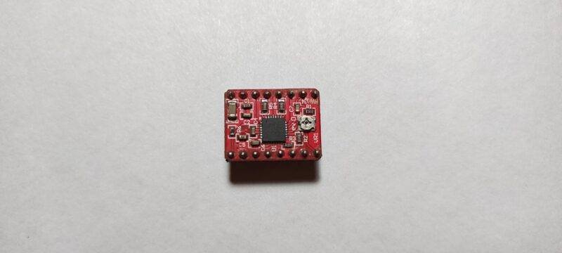


- A4988 is the very common and mostly used stepper motor driver user as many stepper motor drivers or in CNC or 3D printer shield.
- It is actually a breakout board for the A4988 Motor driver DMOS Allegro’s A4988 DMOS Microstepping Driver with Translator and Overcurrent Protection IC.
- It is a Bipolar stepper motor driver, which works perfectly with NEMA stepper motors(as experimented). Also, the logic level for the IC is 3.3V-5V, which is easily accepted by any microcontroller.
- A4988 stepper driver works between the voltage of the 8v to 35V with the current rating of 1A without a heat-sink and2A per coil with a heat-sink and cooling solution.
- It has 5 types of steps resolution from full step, 1/2,1/4,1/8,1/16. Along with under-voltage, over-current, and thermal protection shutdown.
- The schematic of this breakout Board will be soon updated along with the Datasheet, The jumpers available on the Shield will maybe also include as schematics are drawn on the basis of the information on the internet and the datasheet.
JLC PCB Prototype & PCB Fabrication Service
I have assembled the whole circuit on a breadboard. As you know breadboard assembly is not effective for this type of projects. So, JLCPCB offers Rapid PCB Prototyping for Your Research Work. I personally, recommend JLCPCB because you can get your first-try boards right in 24 hours!
The prototyping stage is the most critical period of time for engineers, students, and hobbyists. JLCPCB not only makes your boards quick but also makes your job right as well as cost-effective. This greatly reduces your cost and shortens the time for developing your electronic products.
I am impressed with the quality of the boards, the delivery time, and the cost-effectiveness
DRV8255 Stepper Motor Driver
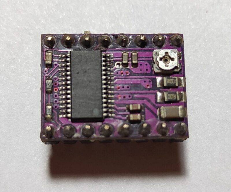
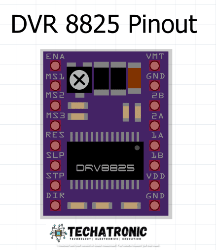

- DRV8825 is another very common and mostly used driver, similar to a4988 stepper motor driver but has some more features or advantages as compared to it.
- It is the breakout board for the Texas Instruments IC DRV8825 in DRV8825 stepper motor driver , which is a two H-bridge Microstepping drivers and a micro-stepping indexer.
- Furthermore, it is also capable of driving a Bipolar stepper motor with a logic level similar to that of A4988, i.e., 3.3V-5V.
- Its operating voltage is between 8.2V-45V with an operating current of about 2.5A at 24V
- It has more micro-stepping up to 1/32 which is more optimized for small stepper motors like in the DVD writers for DIY projects.
