
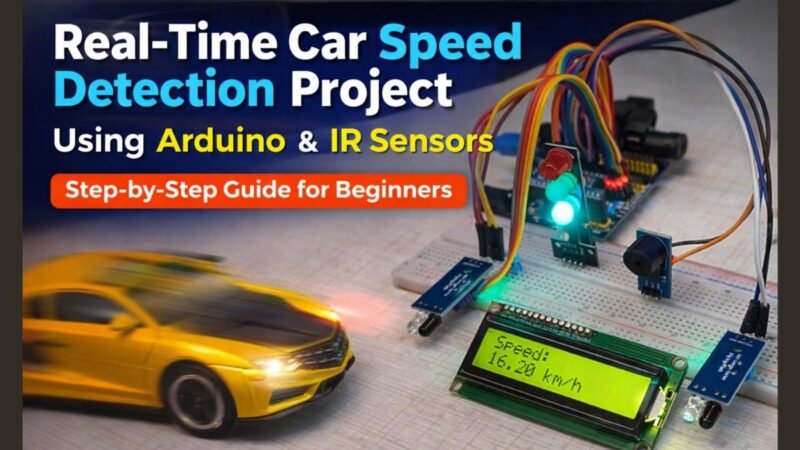
Hey guys, welcome back to the techatronic. in this article, we are going to make a very interesting and trending project, which is Real time car speed detection project.. So this project is very interesting and useful. We are making this project using an IR sensor , display and Arduino. all the deatil about he project hs ben given in this articlke. if you want to learn and make your own project you should read full article.In this Mini Project, we are using two IR sensors. which uses the speed X distance formula.
If yo are new in the electronics, you should learn some basic electroincs and arduino coding, which can help you to make a lot of project. Though this project is very easy to make. Only you have to follow the given steps. here we have shared the other details like Circuit and Code.
Introduction
We are going to build a very interesting and trending electronics project — a Real time car speed detection project using Arduino. This project is not only exciting to create but also highly practical, as similar systems are used in traffic monitoring and speed control applications in real life.
In this project, we use an Arduino board, two IR (Infrared) sensors, and a display module to measure and show the speed of a moving object, such as a toy car or any small vehicle. The working principle of this project is based on a simple physics formula: Speed = Distance / Time.
Here’s how the system works: we place two IR sensors at a fixed distance apart. When a car passes the first IR sensor, the Arduino starts counting time. As soon as the car reaches the second IR sensor, the timer stops. Since we already know the distance between the two sensors, the Arduino calculates the speed using the measured time and then displays the result on the screen in real-time.
This project is perfect for beginners as well as intermediate learners in electronics. If you are new to this field, it is highly recommended to first understand some basic electronics concepts such as sensors, resistors, and circuit connections. Additionally, having a basic knowledge of Arduino programming will make it easier for you to understand and modify the code used in this project.
Even though this project sounds advanced, it is actually quite simple to build. You just need to carefully follow the step-by-step instructions provided in the article. All the important details such as the circuit diagram, component list, connections, and Arduino code have been explained clearly to help you complete the project without confusion.
To make this Awesome Project we need Required Components First.
Required Material for Real time car speed detection project.:-
- Arduino nano
- Arduino nano Shield
- Jumper wires
- IR Sensor-2
- I2C LCD 16X2
- Arduino Nano Cable
- LED Module
- Buzzer Module
Now we need a Circuit Diagram for Real Time speed Monitoring project. with the help of the circuit diagram we can complete the wiring and assembly of our project.
Real Time Car Speed Detection Project Circuit Diagram
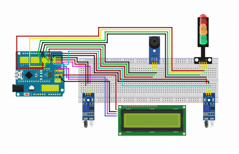
Here We have shared the Circuit diagram. if you need a circuit explanation, we will share too.
📍 Connections:
- VCC → 5V
- GND → GND
- OUT → Digital Pins (likely D2 & D3)
🧠 Working:
- Sensor 1 detects object → start time
- Sensor 2 detects object → stop time
- Arduino calculates speed using: Speed = Distance / Time
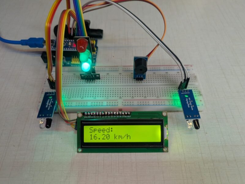
3️⃣ LCD Display (16×2 with I2C)
This is used to show real-time speed.
📍 Connections:
- VCC → 5V
- GND → GND
- SDA → SDA →A4
- SCL → SCL → A5
🧠 Function:
- Displays:
- “Speed: XX km/h”
- Uses I2C → fewer wires (very efficient)
4️⃣ Buzzer Module 🔊
- Used for alert system
📍 Connections:
- VCC → 5V
- GND → GND
- Signal → Digital pin (e.g., D4)
🧠 Function:
- Beeps when:
- Speed exceeds limit
- Object detected
5️⃣ Traffic Light LED Module 🚦
This is a very cool addition 🔥
📍 Connections:
- Each LED pin → Arduino digital pins
- GND → GND
🧠 Function:
- 🔴 Red → High speed (danger)
- 🟡 Yellow → Medium speed
- 🟢 Green → Safe speed
Complete Working Flow
- Car passes IR Sensor 1
- Timer starts
- Car passes IR Sensor 2
- Timer stops
- Arduino:
- Calculates time difference
- Applies formula
- Converts to km/h
- Output:
- Speed shown on LCD
- LED indicates speed level
- Buzzer alerts if needed
Here I have shared all the details for the circuit diagram. Now, you need a code that can run this project.
Real time car speed detection project Arduino Code
#include <Wire.h>
#include <LiquidCrystal_I2C.h>

LiquidCrystal_I2C lcd(0x27, 16, 2);

const int sensor1 = 2;
const int sensor2 = 3;

unsigned long time1 = 0;
unsigned long time2 = 0;
float speed = 0;

// Distance between sensors (in meters)
float distance = 0.2;  // 20 cm

void setup() {
  pinMode(sensor1, INPUT);
  pinMode(sensor2, INPUT);

  lcd.init();
  lcd.backlight();

  lcd.setCursor(0,0);
  lcd.print("Speed Monitor");
  delay(2000);
  lcd.clear();
}

void loop() {

  if (digitalRead(sensor1) == LOW) {
    time1 = millis();

    // Wait for second sensor
    while (digitalRead(sensor2) == HIGH);

    time2 = millis();

    float timeTaken = (time2 - time1) / 1000.0; // seconds

    speed = distance / timeTaken; // m/s
    speed = speed * 3.6; // convert to km/h

    lcd.clear();
    lcd.setCursor(0,0);
    lcd.print("Speed:");

    lcd.setCursor(0,1);
    lcd.print(speed);
    lcd.print(" km/h");

    delay(2000);
  }
}
The code is given above
Code explanation.
Libraries
#include <Wire.h>
#include <LiquidCrystal_I2C.h>
Wire.h→ Used for I2C communicationLiquidCrystal_I2C.h→ Controls the LCD display
2. LCD Initialization
LiquidCrystal_I2C lcd(0x27, 16, 2);
0x27→ I2C address of LCD16, 2→ 16 columns, 2 rows
Pin Definitions
const int sensor1 = 2;
const int sensor2 = 3;
- IR Sensor 1 → Pin 2
- IR Sensor 2 → Pin 3
Variables
unsigned long time1 = 0;
unsigned long time2 = 0;
float speed = 0;
float distance = 0.2;
time1→ Time when object hits sensor 1time2→ Time when object hits sensor 2distance→ Distance between sensors (in meters)
👉 Example: 0.2 = 20 cm
Setup Function
void setup() {
  pinMode(sensor1, INPUT);
  pinMode(sensor2, INPUT);  lcd.init();
  lcd.backlight();  lcd.setCursor(0,0);
  lcd.print("Speed Monitor");
  delay(2000);
  lcd.clear();
}
What happens here:
- Set sensors as input
- Start LCD
- Turn ON backlight
- Display: Speed Monitor
- Wait 2 seconds
- Clear screen
Main Loop
void loop() {
This runs continuously.
Detect First Sensor
if (digitalRead(sensor1) == LOW) {
  time1 = millis();
- When object crosses Sensor 1
- Arduino stores current time using
millis()
👉 millis() = time since Arduino started (in milliseconds)
Wait for Second Sensor
while (digitalRead(sensor2) == HIGH);
- Arduino waits until object reaches Sensor 2
Capture Second Time
time2 = millis();
- When object hits sensor 2 → store time
Calculate Time Difference
float timeTaken = (time2 - time1) / 1000.0;
- Subtract both times
- Convert milliseconds → seconds
Calculate Speed
speed = distance / timeTaken;
speed = speed * 3.6;
Step-by-step:
- Speed = distance / time → (m/s)
- Multiply by 3.6 → convert to km/h
👉 Final output = km/h
Display on LCD
lcd.clear();
lcd.setCursor(0,0);
lcd.print("Speed:");lcd.setCursor(0,1);
lcd.print(speed);
lcd.print(" km/h");
LCD shows:
Speed:
45 km/h
Delay
delay(2000);
- Wait 2 seconds before next reading
Now you have to u pload the code. first you need a software
Arduino IDE which can be downlooad from the given link- Download Arduino IDE
Now, you can upload the program to your Arduino- How to Upload a Program in Arduino
FAQ
How does this project calculate speed?
How does this project calculate speed?
The system uses the formula:
Speed = Distance ÷ Time
Why are two IR sensors used?
Two IR sensors are used to:
Detect the start point (Sensor 1)
Detect the end point (Sensor 2)
Does lighting affect IR sensors?
Yes, IR sensors can be affected by:
Sunlight
Is this project beginner-friendly?
Yes, this project is beginner friendly
Video Sample