Table of Contents
Introduction
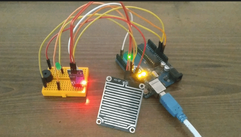
Suppose you are inside your house or you are sleeping and suddenly rain comes and you didn’t get up at that time and your clothes or some important things got wet. So to make people aware of the rain, today we are going to make an Arduino Mini Project rain sensor alarm that will react to mild showers also. There are many rain detectors or triggers available in the market which is a bit costly and bulky. but we are here to make it simple like a DIY thing and if you like it you can also convert it into a PCB and order it on any PCB ordering site.
We are going to use rain sensors available in the market easily. It is relatively cheaper and easy to hook up to any microcontroller and use it.

DESCRIPTION: –
The components we are going to use are all-time basic ones like ARDUINO UNO or any other similar microcontroller. But the special or main item we are going to use today is the rain sensor module. It comes in two parts one is the plate PCB or the detector on which raindrops will fall and the other is the amplifier + comparator circuit which sends data to the microcontroller. this is the coolest Arduino-based mini-project. Like all other sensors, it also has an on-board power led and onboard status led which will glow/blink on detection of rain.
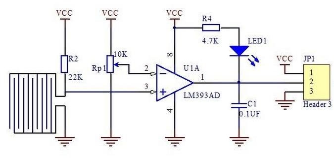
The sensor gives both digital and analog output. The difference between the two is very simple in digital output only high or low means either 1 or 0 is transmitted to the microcontroller but in the analog signal, a wide range of values from 0 to 1023 is transmitted to the microcontroller which relates to the intensity of the rain (mild showers or heavy rain). The sensor is built out of LM393 IC which has an inbuilt amplifier that amplifies the voltage signal to a detectable range. Also, it has voltage comparators for efficient amplification. The amount of amplification can be adjusted with the help of potentiometers given on the sensor.
*NOTE: – AS PCB PART IS EXPOSED TO ENVIRONMENT IT MAY CORRODE EASILY SO BE CAREFUL WHILE USING IT.

RAIN SENSOR SCHEMATIC DIAGRAM: –

FEATURES AND APPLICATIONS: –
- The sensitivity of Rain is great
- Easy to assemble and use
- Adjustable value
- Low price
- Can be used in various projects or in the household also
SENSOR SPECIFICATIONS: –
COMPONENTS NEEDED: –
- Arduino Uno -BUY LINK
- A red led-BUY LINK
- A Rain sensor-BUY LINK
- A breadboard-BUY LINK
- Jumper wires-BUY LINK
- 220ohm resistor-BUY LINK
- A buzzer-BUY LINK

Components Table/buy link
| S.No | Component Required | Quantity | Buy Link |
| 1. | Arduino UNO | 1 | https://amzn.to/3ue2vmh |
| 2. | Arduino UNO Cable | 1 | https://amzn.to/3obXjht |
| 3 | Rain Sensor | 1 | https://amzn.to/3aaBTJy |
| 4. | Buzzer | 1 | https://amzn.to/3Bh9o8I |
| 5. | LED | 3 | https://amzn.to/3AQbzzY |
| 6. | 220-ohm Resistor | 3 | https://amzn.to/3oioZkQ |
| 7. | Jumper Wire | 40 | https://amzn.to/39q43jr |
| 8. | Breadboard | 1 | https://amzn.to/39vsRX2 |
| 9. | 5V DC Adaptor For Arduino | 1 | https://amzn.to/3l2taza |
RAIN SENSOR ARDUINO CIRCUIT DIAGRAM:

Connection Table
| Arduino UNO | Rain Sensor | |
| ( +5V ) | VCC | |
| GND | GND | |
| D3 Pin ( SDA ) | D0 Pin | |
| Arduino UNO | LED | 220-ohm Resistor |
| D8 Pin | Anode Terminal | |
| GND | Terminal 1 | |
| Cathode Terminal | Terminal 2 |
the above circuit is only for the led and the next image is for the buzzer also. in schools, the robotics subject is updated and this is the basic Arduino school project in this course or subject so, you can use both circuit diagrams.

Connection Table
| Arduino UNO | Rain Sensor | ||
| ( +5V ) VCC | VCC | ||
| GND ( Ground ) | GND | ||
| D3 Pin ( SDA ) | D0 Pin | ||
| Arduino UNO | Buzzer | ||
| D10 Pin | Positive Terminal | ||
| GND ( Ground ) | Negative Terminal | ||
| D3 Pin ( SDA ) | D0 Pin | ||
| Arduino | LED R | LED G | 220 Ohm Resistor |
| D12 Pin | Anode Pin | ||
| D11 Pin | Anode Pin | ||
| Cathode Pin | Cathode Pin | Terminal 1 | |
| GND | Terminal 2 |
First, take the power lines onto the breadboard from the microcontroller
VCC/5v–>+ line and GND–> – line.
Then connect the sensor onto the breadboard and connect power to the sensor from powerlines using jumper wires.
Now connect D0 PIN OF SENSOR TO MICROCONTROLLER DIGITAL PIN 3.
Now connect led to the breadboard + to digital pin 12 of Arduino and – to and in series with 220-ohm resistor. Moreover, we can enhance this version by adding a buzzer to it also like in the above diagram. Connect -live of the buzzer to GND on a breadboard, and +tive pin 10 of Arduino also connect a green led same as the red led with +tive pin to pin 11 of Arduino to make this Arduino mini-project.
RAIN SENSOR ARDUINO CODE: –
 //put this code in the ide of arduino from this line
 int LED = 12;
 int Rain_sensor = 3;
 int Rain_detected;
 void setup()
      {
         Serial.begin(9600);
         pinMode(LED, OUTPUT);
         pinMode(Rain_sensor, INPUT);
      }
     void loop()
      {
          Rain_detected = digitalRead(Rain_sensor);
          Serial.println(Rain_detected);
          delay(500);
          if (Rain_detected == 0)
          {
             Serial.println("Rain detected...! take action immediately.");
             digitalWrite(LED, HIGH);
           }
          else
           {
             Serial.println("No Rain detected. stay cool");
             digitalWrite(LED, LOW);
        }
      }
       //For buzzer put this code in Arduino IDE
       int Red_Led   = 12;
       int Green_LED = 11;
       int Buzzer    = 10;
       int Rain_sensor = 3;
       int Rain_detected;
       void setup()
       {
         Serial.begin(9600);
         pinMode(Red_Led, OUTPUT);
         pinMode(Green_LED, OUTPUT);
         pinMode(Buzzer, OUTPUT);
         pinMode(Rain_sensor, INPUT);
       }
       void loop()
       {
          Rain_detected = digitalRead(Rain_sensor);
          Serial.println(Rain_detected);
          delay(500);
          if (Rain_detected == 0)
         {
           Serial.println("Rain detected...! take action immediately.");
           digitalWrite(Red_Led, LOW);
           digitalWrite(Green_LED, HIGH);
           digitalWrite(Buzzer, HIGH);
         }
         else
         {
           Serial.println("No Rain detected. stay cool");
           digitalWrite(Red_Led, HIGH);
           digitalWrite(Green_LED, LOW);
           digitalWrite(Buzzer, LOW);
         }
       }
WORKING: –
As the code starts it initializes the pin to which the sensor sends its data. Then is setup we define the type of function we want on the initialized pins like input or output. Then in the loop, we read the data available on pin 3 and then print that value on our monitor. We also check for the condition of sensor data to be either high or low and according to the condition led glows and turns off. if you are searching for a mini project using Arduino and you need to know only some basics of Arduino and basic electronics.
In buzzer code, we also initialize buzzer pin to pin 10 and led +tive pin to pin 10, and set pin mode to OUTPUT in the setup section. In the loop section along with the led we switch Buzzer also high and low. By this a simple DIY alcohol detector is complete and it can be used in various places.
you need to upload code in Arduino with the help of Arduino ide software.
