Table of Contents
Introduction
Hello guys, welcome back to Techatronic. Are you looking for a magnetic field detector circuit using Arduino, if yes then you are in the right place?
This article will discuss how you can make a magnet detector with a Hall effect sensor using Arduino.
The project that we are going to make has a buzzer and an LED which goes on when the sensor detects any strong or weak magnetic field.
Do you want to make more amazing projects based on Arduino, you can read our articles. We are using an Arduino UNO microcontroller and a KY-024 linear magnetic Hall effect sensor module for this project.
The sensor comes with two inbuilt LEDs, one for indicating power and the other for indicating the magnetic field’s presence. Complete the circuit and then upload the code to the Arduino.

How Does it Work?
The KY-024 magnetic Hall effect sensor is used to detect the magnetic field generated by a magnet.
in this Arduino project, Its output changes according to the field detect by it were there strong or high. You can check the output in both analogs as well as in digital connection.
- When you place a magnet near the sensor the buzzer starts beeping and the LED turns on.
- Hence, it detects the presence of a magnetic field near it.
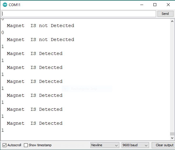
- The output is also displayed on the Arduino serial monitor screen.
- You can locate the serial monitor by viewing the given image.

Simulation


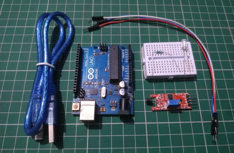
Components Required
| Arduino UNO | BUY LINK |
| KY-024 Hall effect sensor | BUY LINK |
| USB cable for uploading the code | BUY LINK |
| Jumper wires | BUY LINK |
| Breadboard | BUY LINK |
| Buzzer | BUY LINK |
| LED | BUY LINK |
| 220-ohm resistor | BUY LINK |

Circuit Diagram for the Project
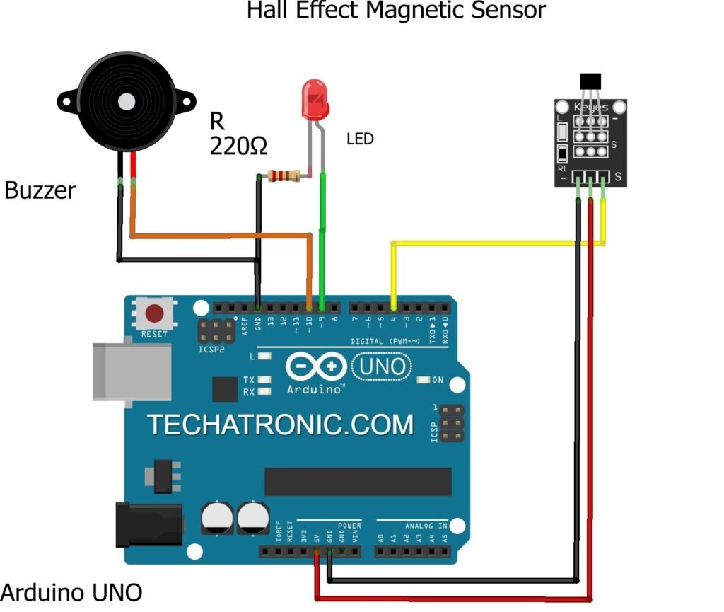
Circuit diagram for Digital connection

Connection table
| Arduino UNO | Hall Effect Sensor | |
| ( +5V ) | ( + ) Positive | |
| GND | ( – ) Positive | |
| D4 Pin | ( S ) Signal | |
| Arduino UNO | Buzzer | |
| GND | Negative ( – ) | |
| D10 Pin | Positive ( + ) | |
| Arduino UNO | LED | 220-ohm Resistor |
| D9 Pin | Anode Terminal | |
| GND | Terminal 1 | |
| Cathode Terminal | Terminal 2 |
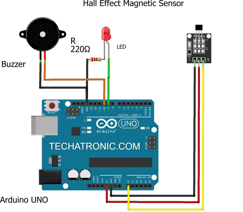
Circuit diagram for Analog connection

Connection table for analog
| Arduino UNO | Hall Effect Sensor | |
| ( +5V ) | ( + ) Positive | |
| GND | ( – ) Positive | |
| A0 Pin | ( S ) Signal | |
| Arduino UNO | Buzzer | |
| GND | Negative ( – ) | |
| D10 Pin | Positive ( + ) | |
| Arduino UNO | LED | 220-ohm Resistor |
| D9 Pin | Anode Terminal | |
| GND | Terminal 1 | |
| Cathode Terminal | Terminal 2 |
There are two types of circuit diagrams given here. You have to make the circuit according to the diagram given above.
- Connect the 5-volts pin of the Arduino to the VCC of the Hall effect sensor.
- Attach the GND pin of the Arduino to the GND pin of the Hall effect sensor.
- Join the positive leg of the LED to the digital-9 pin of the Arduino.
- Connect the negative leg of the LED to the GND of the Arduino through a 220-ohm resistor. A
- ttach the positive wire of the buzzer with the digital-10 pin of the Arduino and the negative wire of the buzzer with the GND of the Arduino.
- Till now the connections are common for both of the configurations.
- You can use a breadboard for making common connections.
- For the Digital connection connect the D0 pin of the sensor to the digital-4 pin of the Arduino and for the Analog connection connect the A0 pin of the sensor to the analog-0 pin of the Arduino.
Once the connections are made properly then upload the given code.
Code for the Project
NOTE: Please upload the code given below to the Arduino. Make sure that you have to upload the code according to the circuit you made.
Code for Digital connection
 //Techatronic
 int val = 0 ;
 void setup()
 {
  Serial.begin(9600);   // sensor buart rate
  pinMode(4,INPUT);    // Hall Effect Sensor connect D4 Pin
  pinMode(9,OUTPUT);   // LED connect D9 Pin
  pinMode(10,OUTPUT);   // Buzzer connect D10 Pin
 }
 void loop()
 {
  val = digitalRead(4); //Hall Effect Sensor Connect A0 pin
  Serial.println(val); // see the value in serial mpnitor in Arduino IDE
  delay(100);
  if(val == 1 )
  {
    digitalWrite(9,HIGH); // LED ON
    tone(10, 300);     // Buzzer ON
    Serial.println(" Magnet IS Detected ");
  }
  else
  {
   digitalWrite(9,LOW);  // LED OFF
   noTone(10);      // Buzzer OFF
   Serial.println(" Magnet IS not Detected ");
  }
 }
Code for Analog connection
 // TECHATRONIC.COM
 void setup()
 {
  Serial.begin(9600);   // sensor buart rate
  pinMode(9,OUTPUT);   // LED connect D9 Pin
  pinMode(10,OUTPUT);   // Buzzer connect D10 Pin
 }
 void loop()
 {
  int s1=analogRead(A0); //Hall Effect Sensor Connect A0 pin
  Serial.println(s1);
  delay(500);
  if( s1 < 480 )
  {
    digitalWrite(9,HIGH); // LED ON
    tone(10, 300);     // Buzzer ON
    Serial.println(" Magnet IS Detected ");
  }
  else
  {
   digitalWrite(9,LOW);  // LED OFF
   noTone(10);      // Buzzer OFF
   Serial.println(" Magnet IS not Detected ");
  }
 }
The Magnet Detector Look Like this

Hope you understand the project well and you must try to make it on your own. If you are facing any errors do inform us in the comments section below. Please check out more Tutorials on Arduino and Raspberry pi.
HAPPY LEARNING!