

Make this awesome project by yourself with all details, Hey guys welcome back to the techatronic. i am here to help you to make a very beautiful LED Magic Effect Project Using Arduino. this is a very simple and interesting project which can make you a magician, alike. you can control the led with you hand gesture like you are doing some magic trick. Because fun is also important in the Study. We brought this project for your learning purposes.This project alow your hand to control the LED. We need many things to make this project, from hardware to software. We need electronic components and software required to upload and write the code. all the detail we are going to share here. also we will provide the youtube video for the same project. so, if you want to learn project you need to read full article.
Introduction of LED Magic Effect
The Arduino LED Chaser with Dual IR Sensors is a visually engaging and interactive project that creates a stunning, magic-like light effect using simple electronic components. In this project, 15 LEDs are arranged in a straight line on a breadboard, while two IR sensors are placed at both ends. The direction of the LED movement changes based on hand gestures, making the system responsive and fun to interact with.
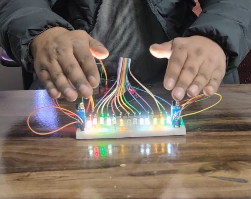
When a hand is placed in front of the left IR sensor, the LEDs begin to glow one by one from left to right, creating a smooth chasing effect across the breadboard. Similarly, when the right IR sensor detects a hand, the LED sequence reverses direction and runs from right to left. This bidirectional control gives the illusion that the lights are being magically pulled in the direction of the hand movement.
This project is an excellent example of how Arduino can be used to combine sensors and outputs to build interactive systems. The IR sensors act as input devices that detect obstacles or hand presence, while the Arduino processes this information and controls the LEDs accordingly. The result is a responsive lighting effect that reacts instantly to user interaction.
From an educational point of view, this project helps beginners understand key concepts such as digital input/output control, sensor interfacing, conditional logic, and LED sequencing. It is also ideal for demonstrations, exhibitions, and learning labs, where visual effects play a crucial role in attracting attention.
Overall, this LED chaser project is simple to build, cost-effective, and highly customizable. By adjusting the number of LEDs, speed of the chase, or sensor sensitivity, users can create unique visual patterns. Whether you are a student, hobbyist, or electronics enthusiast, this project is a perfect blend of creativity, logic, and real-world electronics application.
Now we are going to make the project after the introduction.to make this project, we need some electronics as given as below.
Required Components for LED Magic Effect
| Component Name | Buy Link |
| Arduino uno | BUY NOW |
| LED | BUY NOW |
| IR sensor | BUY NOW |
| Jumper Wire | BUY NOW |
| Resistor | BUY NOW |
| Arduino cable | BUY NOW |
Buy all components together – BUY MAGIC LED KIT
After getting detail of the required components, we need a connection diagram which helps us to make the components together.
LED Magic Effect Project Circuit Diagram
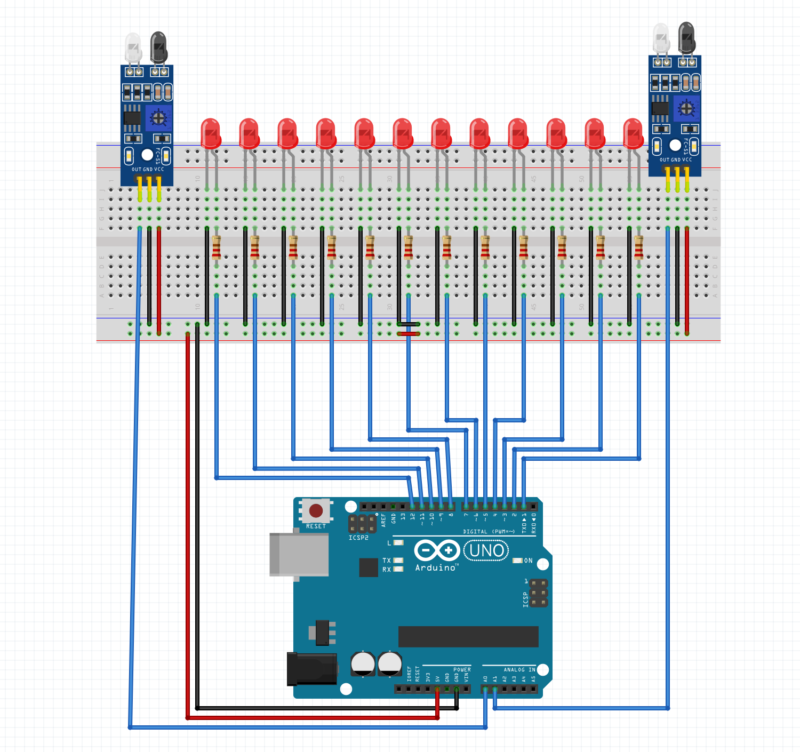
Circuit Explanation: Magic LED Effect Kit
This circuit is designed to create a bidirectional LED chaser effect using an Arduino UNO, 15 LEDs, and two IR obstacle sensors placed at both ends of a breadboard. The direction of the LED movement depends on which IR sensor detects a hand.
1. Power Supply and Ground Connections
The Arduino UNO provides power to the entire circuit.
- The 5V pin of the Arduino is connected to the positive (red) power rail of the breadboard.
- The GND pin is connected to the negative (blue/black) rail.
Both IR sensors and all LEDs share the same common ground, ensuring stable and correct operation.
2. LED Connections (15 LEDs)
- Fifteen LEDs are placed in a straight line on the breadboard to form the chaser effect.
- Each LED is connected in series with a current-limiting resistor (typically 220Ω or 330Ω) to protect the LED from excessive current.
- One terminal of each LED is connected to an individual digital output pin of the Arduino using blue jumper wires.
- The other terminal of each LED is connected to ground through its resistor.
This setup allows the Arduino to control each LED independently, turning them ON and OFF in sequence to create smooth running light patterns.
3. IR Sensor Connections (Left and Right)
Two IR sensors are mounted at the left and right ends of the breadboard.
Each IR sensor has three pins:
- VCC → connected to Arduino 5V
- GND → connected to Arduino GND
- OUT → connected to an Arduino digital or analog input pin
When a hand is placed near a sensor, its OUT pin changes state, signaling the Arduino.
4. Working Principle
- When the left IR sensor detects a hand, the Arduino executes code to turn ON LEDs sequentially from left to right.
- When the right IR sensor is triggered, the Arduino reverses the sequence, running LEDs from right to left.
- Only one direction runs at a time, creating a magic-like interactive lighting effect.
After making the connection we need a code which run our project.
LED Magic Effect Arduino code
the code is given above now we need to upload the cod, there is a tutorial on how to downlod the code into the arduino. if still you have any problem do ask us in the comment section.
Working of LED Magic Effect Project
The LED Magic Effect Project is designed to create a visually attractive lighting pattern using an Arduino, multiple LEDs, and IR sensors. The project works on the principle of object detection and directional control, where the LEDs glow in different directions based on which sensor detects an object.
In this project, multiple LEDs are connected in a straight line on a breadboard. Two IR sensors are placed at both ends of the LED arrangement—one on the left side and the other on the right side. These sensors continuously monitor the presence of any object, such as a hand, in front of them.
When an object comes close to the left IR sensor, the sensor detects the obstruction and sends a signal to the Arduino. The Arduino then activates the LEDs starting from the leftmost LED and gradually turns them ON one by one toward the right side. This creates a smooth running or chasing light effect from left to right.
Similarly, when an object is detected by the right IR sensor, the Arduino responds by turning ON the LEDs from the rightmost LED toward the left. This produces a reverse running LED effect, giving the impression that the light is moving in the opposite direction.
If both IR sensors detect an object at the same time, the Arduino triggers a special lighting pattern. In this condition, LEDs from both ends start glowing simultaneously and move toward the center. This dual-direction lighting effect enhances the visual appeal of the project and demonstrates intelligent control logic.
If no object is detected by either sensor, all LEDs remain turned OFF, which helps save power and avoids unnecessary illumination.
Overall, the LED Magic Effect Project demonstrates how sensors, microcontrollers, and LEDs can be combined to create interactive and intelligent lighting systems. It is ideal for decorative lighting, smart displays, and beginner-level Arduino learning projects.