
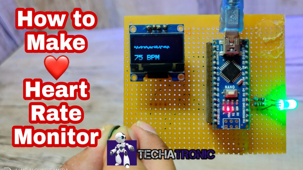
Heart Rate Monitor
How does it work?
In this paragraph, we will see the working of the heart rate monitor and sensor. the pulse rate sensor having a green color light on which we have to put our finger so that the light can incident on our skin. after that, the sensor read the value and sens this value to the Arduino. Arduino process on this value and after all the calculation it send the data to OLED display to show. OLED display is black and white display that can only show the white colour in the text as well as in the animation. so I am using them both. 128×64 pixel content in this tiny OLED. so it can show you the 128 characters at a time.
OLED display is more attractive than the old 16X2 display and having more pixels so that it can show more character than the LCD. and it can directly communicate with the I2C Protocol. so, it needs only two wires to communicate with the controller. but the drawback is the pixel size. the words displaying into the display are too short to see. Now talk about the Heart rate sensor. Heart rate sensor work on the optical principle. there are one light and one photodiode that sense the light intensity. the sensitivity is very high of this photodiode so that can easily sense the low-intensity light also. now, when we place our finger at the top of the sensor the light incident from the light source on the finger and back to the photodiode. when the blood suddenly increases the light sense by the photodiode also be change. so that the sensor can send this data to the process. this is how the heart rate monitor systems work. there are one more OLED display project gas leakage detector
Components Required for Heart Rate Monitor
S.No
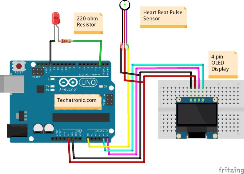
Schematic Diagram for Heart Rate Monitor

Arduino pulse rate monitor circuit diagram
|
Arduino UNO |
Oled Display |
|
|
D2 Pin ( SDA Pin ) |
SDA Pin |
|
|
D1 Pin ( SCL Pin ) |
SCL Pin |
|
|
( +5V ) VCC |
VCC |
|
|
GND ( Ground ) |
GND |
|
|
Arduino UNO |
Pulse sensor |
|
|
A0 Pin |
OUT Pin |
|
|
( +5V ) VCC |
VCC |
|
|
GND ( Ground ) |
GND |
|
|
Arduino |
LED G |
220 Ohm Resistor |
|
D2 Pin |
|
|
|
GND |
|
Terminal 1 |
|
|
Cathode Pin |
Terminal 2 |
Arduino Code for Heart Rate Monitor
#include <Adafruit_SSD1306.h>
#define OLED_Address 0x3C
Adafruit_SSD1306 oled(1);
int x=0;
int lastx=0;
int lasty=0;
int LastTime=0;
int ThisTime;
bool BPMTiming=false;
bool BeatComplete=false;
int BPM=0;
#define UpperThreshold 560
#define LowerThreshold 500
void setup() {
oled.begin(SSD1306_SWITCHCAPVCC, OLED_Address);
oled.clearDisplay();
oled.setTextSize(2);
}
void loop()
{
if(x>127)
{
oled.clearDisplay();
x=0;
lastx=x;
}
ThisTime=millis();
int value=analogRead(0);
oled.setTextColor(WHITE);
int y=60-(value/16);
oled.writeLine(lastx,lasty,x,y,WHITE);
lasty=y;
lastx=x;
// calc bpm
if(value>UpperThreshold)
{
if(BeatComplete)
{
BPM=ThisTime-LastTime;
BPM=int(60/(float(BPM)/1000));
BPMTiming=false;
BeatComplete=false;
tone(8,1000,250);
}
if(BPMTiming==false)
{
LastTime=millis();
BPMTiming=true;
}
}
if((value<LowerThreshold)&(BPMTiming))
BeatComplete=true;
// display bpm
oled.writeFillRect(0,50,128,16,BLACK);
oled.setCursor(0,50);
oled.print(BPM);
oled.print(” BPM”);
oled.display();
x++;
}
there are two library which you have to include in the Arduino IDE
Upload the program into the Arduino and make co0nnection with the help of circuit diagram.
Learn 10+ basic activity & sensor interfacing with our Arduino ebook. Well explained program. And brief circuit diagram WhatsApp and email support. which will help you to learn basic electronics, Arduino Coding, Sensor interfacing with Arduino, Arduino, and much more. buy Arduino Ebook to learn https://techatronic.com/arduino-ebook/
Video Sample