Hello guys, welcome back to Techatronic. We are back with another new post in the series of 555 timer projects. So this time we are going to make a dark detector using a 555 timer ic and LDR.
The dark detector that we made is capable of sensing the light falling on the LDR. We can connect different devices at the output as per our need and it is useful for performing a number of operations. For demonstration purposes, we are using an LED at the output.
The 555 timer has 8 pins and before starting we suggest you see its pin diagram for the automatic street light project. For your convenience, the step-by-step procedure along with the circuit diagram is also given below for making this project. You can also read articles on Arduino and IoT published by us.

Table of Contents
About the Project
- Let us discuss the working of this automatic street light project. We are using an LDR that is a light-dependent resistor in this project so whenever we cover the top of LDR the LED will go on.
- The LED will turn on and off according to the amount of light that falls on the surface of the LDR. Please connect the 5 volts dc supply to the positive and negative rails of the breadboard.
- You can also adjust the sensitivity of the LDR by replacing the 4K7 resistor with some other resistors.
- This circuit can be useful for making projects like automatic street lights. You can also check the PWM dc motor speed controller using 555 timer ic made by us.
Components Required
| LDR | BUY LINK |
| 555 timer ic | |
| Capacitor 100 uF and 0.1 uF | |
| Resistor 1K, 4.7K, and 47K ohm | BUY LINK |
| LED | BUY LINK |
| 5 volts supply |
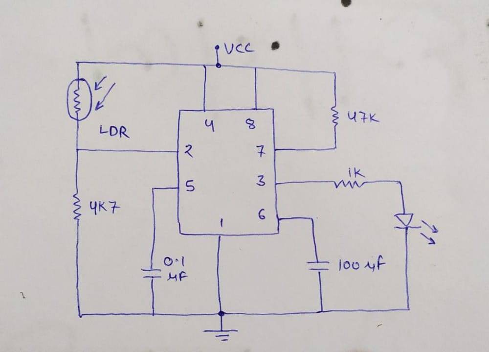
automatic street light project Circuit Diagram

- Put the 555 timer IC on the breadboard and connect its pin number 1 to the negative rail of the breadboard.
- Join pin 8 of the ic to the positive rail of the breadboard.
- Attach pin 4 of the ic with pin number 8. Connect pin 7 of the ic with the positive rail via a 47K resistor.
- Now take an LDR and connect one leg with pin number 2 of the ic and the other leg with the positive rail.
- Join pin number 2 of the ic with the negative rail of the breadboard via a 4K7 resistor.
- Then take a 0.1 uF ceramic capacitor and connect its positive leg with pin number 5.
- Join the negative leg of the capacitor to the negative rail of the breadboard.
- Similarly, connect the positive leg of the 100 uF capacitor with pin 5 of the ic and negative leg to the negative rail.
- As we know that pin 3 is the output pin then take an LED and connect its positive leg with this pin and negative leg with the negative rail. Your circuit is now ready for testing.
Let’s test the circuit
So, we hope that you understand this project completely, and please try to make it on your own. If you have any doubts related to this project then please ask them in the comments section given below. Also, do check out more tutorials on Arduino and Raspberry Pi.
Thanks for reading.
Latest 555 timer projects
water level indicator project Using 555 | 555 Ic Projects
Monostable Multivibrator using 555 timer | 555 Monostable Multivibrator
555 Timer LED Flasher | LED Flasher 555 Timer IC
555 delay timer with ON/OFF | 555 timer delay off circuit
Led Chaser Circuit Using 4017 IC and 555 | 555 timer led chaser