
Blinking an LED using the ESP32 microcontroller and the Arduino Integrated Development Environment (IDE) is a beginner-friendly project that can be used to familiarize oneself with the basics of programming and electronics for esp32 led blink. In this project, we will connect an LED to the ESP32 and write a simple program to make it blink.
Table of Contents
Introduction
It is widely used for various IoT (Internet of Things) projects because of its low cost and high performance. One of the simplest and most basic projects for the ESP32 is a LED blink. In this project, an LED is connected to one of the ESP32’s digital pins and made to turn on and off within a specified interval.
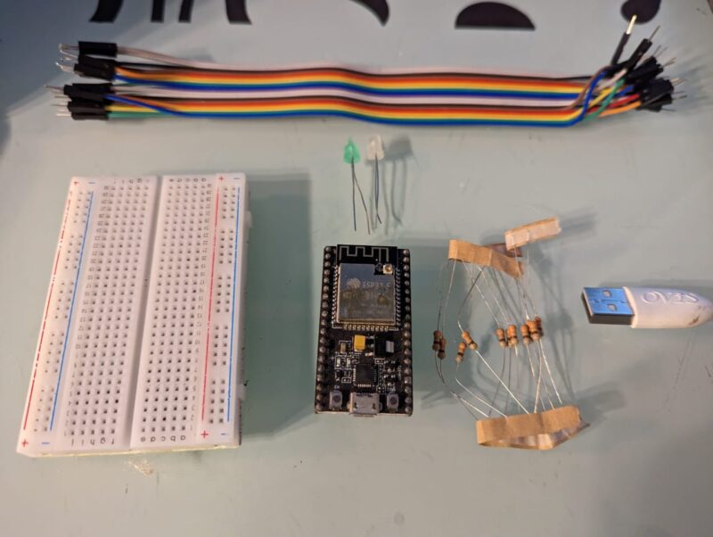
Before we start, let’s make sure that we have all the necessary components and software installed. Here’s a list of things you’ll need:
Components Required for esp32 LED Blink
- Arduino IDE (You can download the latest version of the Arduino IDE from the official Arduino website: https://www.arduino.cc/en/software)
| ESP32 Development Board | BUY LINK |
| LED | BUY LINK |
| 220-ohm resistor | BUY LINK |
| Jumper wires | BUY LINK |
| Breadboard | BUY LINK |
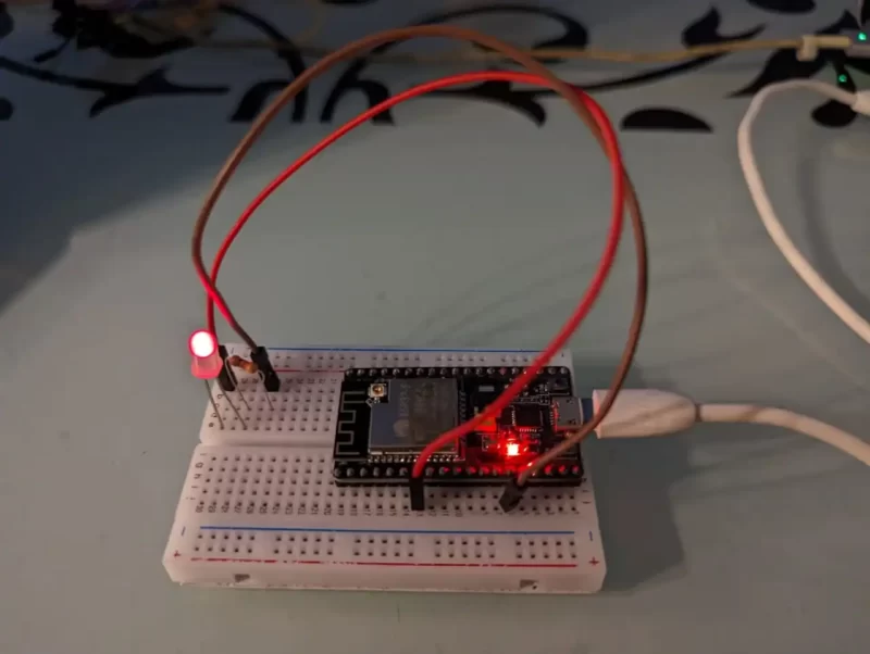
Now that we have all the components, let’s start building the circuit. Connect the positive leg of the LED (the longer leg) to the 220-ohm resistor. Connect the other end of the resistor to pin 5 on the ESP32. Connect the negative leg of the LED (the shorter leg) to GND on the ESP32. The circuit should look something like this:
Once the circuit is built, it’s time to write the code. Open the Arduino IDE and create a new sketch. The first thing we need to do is to include the necessary libraries. Go to the “Sketch” menu, then select “Include Library”, and then “ESP32”.
The basic step to make the circuit
Step 1: Connecting the LED and the resistor to the ESP32
Start by connecting the LED and the resistor to the ESP32 development board. The LED has two legs: the anode and cathode. The anode (positive) is connected to the digital pin and the cathode (negative) is connected to the resistor. The other end of the resistor is connected to the ground pin.
Step 2: Installing the Arduino IDE and the ESP32 Board Package
The next step is to install the Arduino Integrated Development Environment (IDE) and the ESP32 board package. The Arduino IDE is open-source software that makes it easy to write, upload, and debug code for the ESP32. You can download the latest version of the Arduino IDE from the official website.
Once you have installed the Arduino IDE, open it and go to the “Tools” menu. Then, select “Board” and “Boards Manager”. Search for “ESP32” in the search bar and install the ESP32 board package

Next, we need to define the pin to which the LED is connected. In this case, it’s pin 5. We’ll use the const int keyword to define a constant integer variable for the pin number.
const int LED = 5;
Next, we’ll write the setup() function. The setup() the function is called once when the ESP32 boots up. We’ll use this function to initialize the LED pin as an output.
void setup() {
  pinMode(LED, OUTPUT);
}
Now, we’ll write the loop() function. The loop() the function is called repeatedly and is where we’ll write the code to make the LED blink.
void loop() {
  digitalWrite(LED, HIGH);
  delay(1000);
  digitalWrite(LED, LOW);
  delay(1000);
}
The digitalWrite(LED, HIGH) the line turns the LED on by setting the voltage on the LED pin to high. The delay(1000) line causes the program to wait for 1000 milliseconds or 1 second. Then, the digitalWrite(LED, LOW) line turns the LED off by setting the voltage on the LED pin to low. Another delay(1000) line causes the program to wait for another second before repeating the process.
The complete code for the project should look something like this:
ESP32 led blink Arduino Code
#include <Wire.h>
#include <WiFi.h>

const int LED = 5;

void setup() {
  pinMode(LED, OUTPUT);
}

void loop() {
  digitalWrite(LED, HIGH);
  delay(1000);
  digitalWrite(LED, LOW);
  delay(1000);
}
Once the code is written, connect the ESP32 to your computer using a USB cable. Go to the “Tools” menu, then select