
He guys welcome back to the Techatronic. So today we are making a very good project the name of this project is ESP32 RC car tutorial. In this project we are making a remote control car with the help of ESP 32 controller. We have made many RC car before like Bluetooth control RC car gesture control RC car but this time we are using a very powerful controller the ESP 32. The power and speed is much more than the arduino. But this controller works on 3.3v logic. So we have to work very carefully.
Introduction
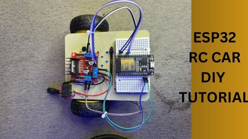
ESP32 RC car will build on a single chassis having two tire and two Motors. Also we will use a single caster Wheel in front. So this is also called the Mini RC car with iot facilities. Although the ESP 32 have Wi-Fi and bluetooth inbuilt in so we have not Required any other wireless device to interface with this project. In this project we are going to use the Bluetooth of ESP 32. So we will connect this ASP 32 with bluetooth wireless communication with our mobile phone app. So the mobile phone app will send data to the ESP 32 via bluetooth.
So now will see how does the ESP32 RC car will work. First of all we have to install an application name RC controller. Now we have to connect the Bluetooth of our mobile to the ESP 32 Bluetooth. After pairing the Bluetooth we have to go to the application. And there we have to connect the application with the pair Bluetooth. Now we have to touch on the buttons forward backward left and right which are given in the mobile application. Now the forward button will send the. ‘F’ and backward button will send the ‘B’. R for right and L for left.
Now all the instruction will be received by ESP 32 controller. And we have written the code according to this instructions like forward backward right and left. So if the controller received F means robot will move forward and to move forward both the Motors rotate in clockwise direction. And if the controller received the B it means the robot have to move backward to move backward proverb will rotate it’s motor anti clockwise.
If the controller will receive the letter R then the robot should move to the right direction. To move into the right direction robot need to rotate the left motor in clockwise and the right motor into the anti clockwise direction.If the controller will receive the letter L then the robot should move to the left direction. To move into the left direction robot need to rotate the left motor in anti clockwise and the right motor into the clockwise direction.
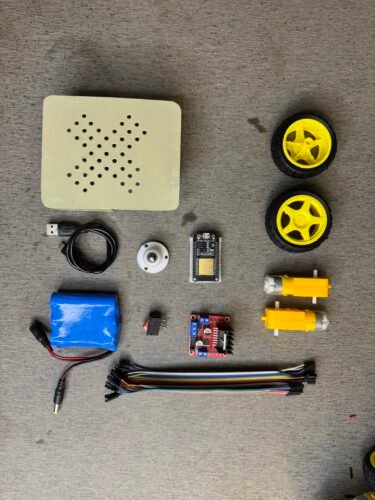
To make this project we need some electronic component and software so here I am going to share the required material list and step by step instruction how to make this project ESP32 RC Car.
ESP32 RC Car Required Components
- ESP32
- Chassis
- Bo motors
- Tires
- Jumper wires
- Switch
- Battery
- Breadboard
- caster wheel
- Esp 32 micro USB Cable
- L298N
| ESP32 | BUY LINK |
| Chassis | BUY LINK |
| Bo motors | BUY LINK |
| Tires | BUY LINK |
| Jumper wires | BUY LINK |
| Switch | BUY LINK |
| Battery | BUY LINK |
| Breadboard | BUY LINK |
| Caster wheel | BUY LINK |
| cable esp32 | BUY LINK |
| L298N | BUY LINK |
After havig the components list we need to know how to connect the components together. So, we have the circuit diagram for now. Here you can buy full kit with manual too – BUY NOW
To buy Complete working robot – BUY NOW
ESP32 RC Car Circuit Diagram

The circuit diagram is made up by fritzing.
Wiring Explanation:
Power Supply:
- Battery Pack (4 x AAA = ~6V) is connected to the power terminals of L298N:
- Red wire (VCC) → 12V Pin on L298N
- Black wire (GND) → GND Pin on L298N
- A push button is added between the battery’s positive line and the L298N’s VCC to act as a switch.
- L298N “5V EN” jumper is likely in place, so it supplies 5V to ESP32 via onboard regulator.
Motor Connections:
- Motor A (left motor) is connected to OUT1 and OUT2 on the L298N
- Motor B (right motor) is connected to OUT3 and OUT4 on the L298N
ESP32 to L298N Motor Driver Control Pins:
- IN1 → GPIO 19 (controls direction of Motor A)
- IN2 → GPIO 21
- IN3 → GPIO 22 (controls direction of Motor B)
- IN4 → GPIO 23
- GND of ESP32 is connected to GND of L298N for a common ground.
⚡ Power to ESP32:
- ESP32 gets 5V from the L298N module’s 5V output pin, allowing the microcontroller to run off the same battery supply.
Now we need Code to start our project we have attached all the components together accoding to the circuit diagram.
ESP32 RC Car Code
// Motor Pins
const int IN1 = 19; // Left motor
const int IN2 = 21;
const int IN3 = 22; // Right motor
const int IN4 = 23;
// Setup Bluetooth Serial
include “BluetoothSerial.h”
BluetoothSerial SerialBT;
void setup() {
// Set motor pins as output
pinMode(IN1, OUTPUT);
pinMode(IN2, OUTPUT);
pinMode(IN3, OUTPUT);
pinMode(IN4, OUTPUT);
// Begin Serial over Bluetooth
SerialBT.begin(“ESP32_Car”); // Name shown in BT app
Serial.begin(9600);
}
void loop() {
if (SerialBT.available()) {
char command = SerialBT.read();
Serial.println(command);
switch (command) {
  case 'F': // Forward
    digitalWrite(IN1, HIGH);
    digitalWrite(IN2, LOW);
    digitalWrite(IN3, HIGH);
    digitalWrite(IN4, LOW);
    break;

  case 'B': // Backward
    digitalWrite(IN1, LOW);
    digitalWrite(IN2, HIGH);
    digitalWrite(IN3, LOW);
    digitalWrite(IN4, HIGH);
    break;

  case 'L': // Left
    digitalWrite(IN1, LOW);
    digitalWrite(IN2, HIGH);
    digitalWrite(IN3, HIGH);
    digitalWrite(IN4, LOW);
    break;

  case 'R': // Right
    digitalWrite(IN1, HIGH);
    digitalWrite(IN2, LOW);
    digitalWrite(IN3, LOW);
    digitalWrite(IN4, HIGH);
    break;

  case 'S': // Stop
    digitalWrite(IN1, LOW);
    digitalWrite(IN2, LOW);
    digitalWrite(IN3, LOW);
    digitalWrite(IN4, LOW);
    break;
}
}
}
So, we have shared the code above. you need to uload the code after all step completed. we have also shared how to upload the code into the esp32 using arduino Ide. if you have any doubt or problem you can visit our website home page