Table of Contents
Introduction
Hello guys, welcome back to Techatronic.
Water pumps play an important role in farming as well as daily household activities. We install them in our homes so that they can pump the groundwater.
Sometimes water pumps are also used to create water pressure. In this article, we are going to make an IoT Smart farming and control it via the Blynk application by using NodeMCU.
We are using a NodeMCU esp8266 and a single channel relay module for turning the pump on and off. You can check out more amazing projects on IoT made by us. You can control the water pump through the app.
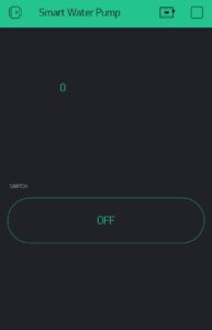
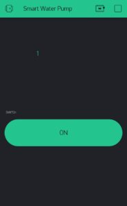
Just write your network’s SSID, PASSWORD, and the unique token number in the code given below. You can also see that if the pump is on or off inside the app. You have to click this button on the screen to turn the pump on or off.
Set up the Blynk app
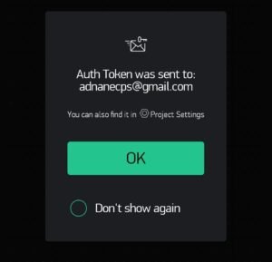
First of all, install the Blynk IoT app on your smartphone and then open it. Sign in to the app and provide your email address so the Blynk app can send a token number to you on your email.
login in app
create new project
Then you will see the page which is given below and you have to select a new project from it.

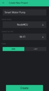
Now name the project according to your choice (Smart Water Pump) and choose the device as NodeMCU. Select the connection type to wifi as given in the image.
Then you can choose what to use in the app. You can add different widgets, buttons, or controllers. Click on the plus button to open the widget box.
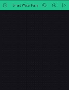
Create a Button
Now from the menu choose a button and a value display widget as shown below.
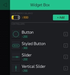
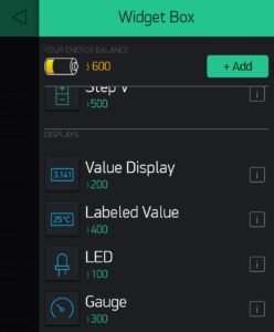
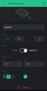
When you successfully add the widgets then go to the button settings and set the pin to virtual 12. You can also name the button.
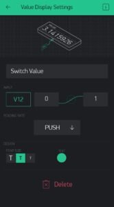
Now do the same for the value display widget. Name it as a switch value and select the V12 pin for it.
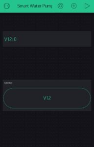
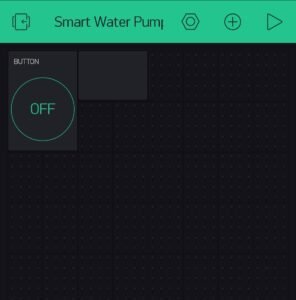
The complete app setup looks like this.
Components Required
- NodeMCU esp8266
- Single-channel relay
- DC water pump
- Push-button
- Jumper wires and a breadboard
- Smartphone with a good internet connection
- 9-volts DC power supply
- USB cable for uploading the code
IoT Smart farming Circuit diagram
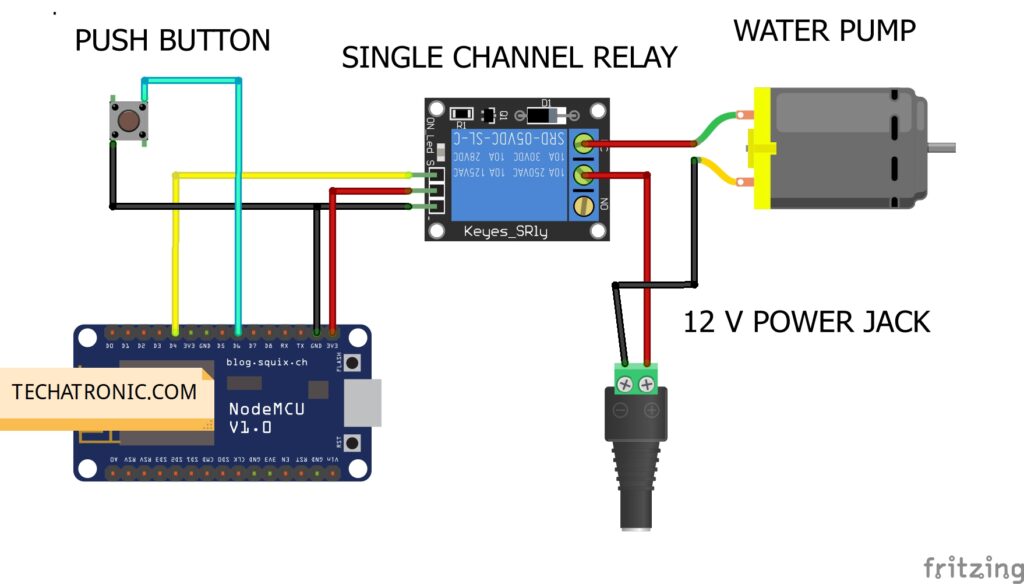
There is a fritzing diagram is given below as you can see you need a relay to interface motor with the nodemcu.all the connection are clean and easy to make.
Connection Table
| Nodemcu esp8266 | 5V Relay Module | |
| VV, Vin | VCC | |
| G, GND | GND | |
| D4 Pin | OUT Pin | |
| Nodemcu esp8266 | Push Button | |
| GND | Terminal 1 | |
| D6 Pin | Terminal 2 | |
| 9 Volt Adaptor | Water Pump | 5V Relay Module |
| Normally Open | ||
| + 9 Volt | Common | |
| Terminal 1 | Normally Closed | |
| – Negative | Terminal 2 |
Make the circuit according to the given diagram.
- 3.3-volts pin of the NodeMCU -> VCC pin of the relay
- GND pin of the NodeMCU -> GND pin of the relay
- digital-4 pin of the NodeMCU -> signal pin of the relay
- digital-6 pin of the NodeMCU -> one side of the pushbutton
- GND pin of the NodeMCU -> another side of the pushbutton
- Pins of the water pump -> one to the negative supply and other to the relay as shown
IoT Smart farming Code
Note: First please install <ESP8266WiFi.h>, <BlynkSimpleEsp8266.h>, <ArduinoOTA.h> libraries to the Arduino and then upload the code to the NodeMCU. Check here how to install zip libraries to the Arduino IDE.
 //TECHATRONIC.COM
 // ESP8266 LIBRARY
 // https://github.com/ekstrand/ESP8266wifi
 #define BLYNK_PRINT Serial
 #include <ESP8266WiFi.h>
 #include <BlynkSimpleEsp8266.h>
 #include <ESP8266mDNS.h>
 #include <WiFiUdp.h>
 #include <ArduinoOTA.h>
 BlynkTimer timer;
 void checkPhysicalButton();
 int relay1State = LOW;
 int pushButton1State = HIGH;
 #define AUTH "P5weseHWDxxkwm-SH0GARQt9lStSl-hF"
 #define WIFI_SSID "DESKTOP"  //Enter WIFI Name
 #define WIFI_PASS "asdfghjkl" //Enter WIFI Password
 #define SERVER "blynk-cloud.com "
 #define PORT 8442
 #define RELAY_PIN_1   D4
 #define PUSH_BUTTON_1  D6
 #define VPIN_BUTTON_1  V12
 #define OTA_HOSTNAME "Home_Automation"
 BLYNK_CONNECTED() {
  // Request the latest state from the server
  Blynk.syncVirtual(VPIN_BUTTON_1);
 }
 // When App button is pushed - switch the state
 BLYNK_WRITE(VPIN_BUTTON_1) {
  relay1State = param.asInt();
  digitalWrite(RELAY_PIN_1, relay1State);
 }
 void checkPhysicalButton()
 {
  if (digitalRead(PUSH_BUTTON_1) == LOW) {
   // pushButton1State is used to avoid sequential toggles
   if (pushButton1State != LOW) {
    // Toggle Relay state
    relay1State = !relay1State;
    digitalWrite(RELAY_PIN_1, relay1State);
    // Update Button Widget
    Blynk.virtualWrite(VPIN_BUTTON_1, relay1State);
   }
   pushButton1State = LOW;
  } else {
   pushButton1State = HIGH;
  }
 }
 void setup()
 {
  Serial.begin(115200);
  Blynk.begin(AUTH, WIFI_SSID, WIFI_PASS,"blynk-cloud.com", 8442);
  ArduinoOTA.setHostname(OTA_HOSTNAME); // For OTA - Use your own device identifying name
  ArduinoOTA.begin(); // For OTA
  pinMode(RELAY_PIN_1, OUTPUT);
  pinMode(PUSH_BUTTON_1, INPUT_PULLUP);
  digitalWrite(RELAY_PIN_1, relay1State);
  // Setup a function to be called every 100 ms
  timer.setInterval(500L, checkPhysicalButton);
 }
 void loop()
 {
  Blynk.run();
  ArduinoOTA.handle();
  timer.run();
 }
Check out more tutorials on Arduino and Raspberry Pi. For any doubts feel free to use the comments section below.
