Table of Contents
Introduction
Hey geeks, welcome back to Techatronic. In this article, we are going to see how you can make your own automatic light using Arduino UNO. We are also using an RCWL0516 microwave sensor in this project. This project is useful for making automatic lights and other home automation projects. You can also check more projects on Arduino and IoT. Just make the circuit according to the given diagram and then upload the code to the Arduino.
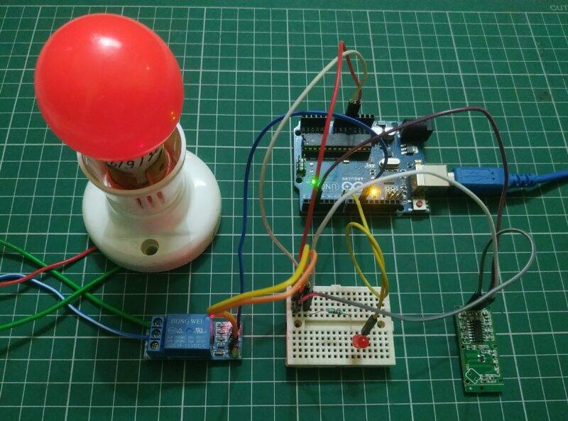
Description
- This sensor can sense the presence of someone near it or we can also say that is just like a motion sensor having a wide sensing angle.
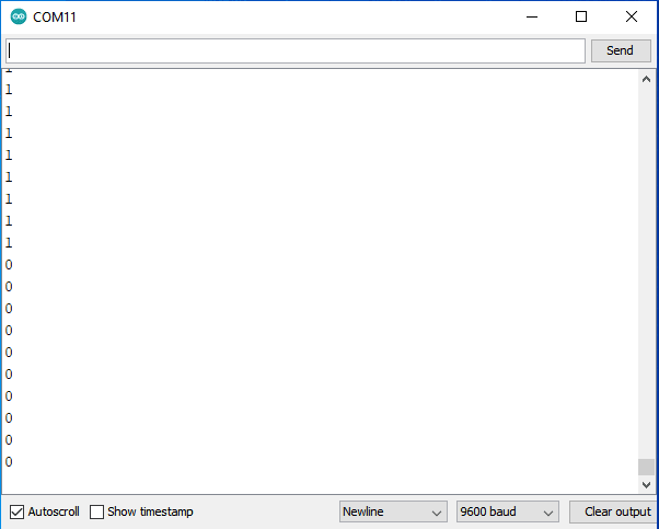
- When it capture the movement in its range then a high signal is generated in microwave motion sensor and you can also see the output generated by it on the serial monitor screen.
- If you are not aware of the interfacing of the relay module with Arduino then go through it first.
- Just open the serial monitor screen which is on the top right corner in the Arduino IDE.
- The LED will turn on automatically when someone come near to the sensor.
- We are using a relay module for operating an AC load.
- You can also check the DC motor speed controller circuit using Arduino made by us.


Components Required
| Arduino UNO | BUY LINK |
| Resistor 220 ohm | BUY LINK |
| LED | BUY LINK |
| RCWL0516 microwave sensor | BUY LINK |
| Jumper wires | BUY LINK |
| Breadboard | BUY LINK |
| Single channel relay | BUY LINK |
| USB cable for uploading the code | BUY LINK |

microwave motion sensor circuit diagram
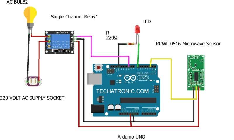
| Arduino UNO | RCWL 0516 Microwave Sensor | |
| 11 Pin | IN Pin | |
| +5 Volt | VCC | |
| GND | GND | |
| Arduino UNO | 5V Relay Module | |
| 2 Pin | D0 Pin | |
| +5 Volt | VCC | |
| GND | GND | |
| Arduino UNO | LED | 220 Ohm Resistor |
| 7 Pin | Anode Terminal | |
| GND | Terminal 1 | |
| Cathode Terminal | Terminal 2 | |
| AC Bulb | Relay Module | Power Supply |
| Normally open | ||
| Common | Phase | |
| Terminal 1 | Normally closed | |
| Terminal 2 | Neutral |

- First of all take a RCWL0516 microwave sensor and connect its VCC pin with the 5 volt pin of the Arduino.
- Then connect the GND pin of the sensor with the GND pin of the Arduino.
- Join the OUT pin of the sensor with the digital-2 pin of the Arduino.
- Now connect the positive leg of the LED with the digital-7 pin of the Arduino.
- Attach the negative leg of the LED to the GND pin of the Arduino via a 220 ohms resistor.
- Connect the VCC pin of the relay module to the 5 volt pin of the Arduino.
- Join the GND pin of the relay module with the GND pin of the Arduino.
- Connect the OUT pin of the relay module with the digital-10 pin of the Arduino.
- To the other pins of the relay module connect an AC bulb and then connect it with the AC supply as shown in the given circuit diagram.
- Make sure that the connections are correct and tight.


Code for Automatic Light by microwave sensor
NOTE: Please upload the code which is given below to the Arduino.
// TECHATRONIC.COM

int val = 0 ;
void setup()
{
Serial.begin(9600);     // sensor buart rate
pinMode(2,INPUT);       // RCWL MicroWave sensor output pin connected to D2
pinMode(7,OUTPUT);      //  led pin
pinMode(10,OUTPUT);     //  Relay PIN

digitalWrite(10,HIGH);  // Relay Normaly OFF

}
void loop()
{
val = digitalRead(2); // RCWL MicroWave output pin connected
Serial.println(val);  // see the value in serial monitor in Arduino IDE
delay(100);

if(val == 1 )
{
digitalWrite(7,HIGH);   // LED ON
digitalWrite(10,LOW);   // Relay ON

}
else
{
digitalWrite(7,LOW);    // LED OFF
digitalWrite(10,HIGH);  // Relay OFF
}
}
We hope that you understand the project completely and now please try to make it on your own. If you have any doubts regarding this project then please do let us know in the comments section given below. Also, do check out more articles on Arduino and Raspberry Pi.
Thanks for reading.




I am using DFRobot_mmWave_Radar sensor. This senses even sleeping person. But the double-antenna pattern has very narrow beam. The single antenna-pattern model should be better, as it has about 120 degrees beam width. Also I have found a Seeed Studio sensor which is very promising, but did not tested yet.
Have you experienced that too?