Hey techies, hope you are doing fine. Have you ever seen the fading effect in LED strips and lights? Did you know how this circuit works? Well, In this 555 timer project we are here to discuss the working of an LED Brightness Control using a potentiometer with you guys.
Table of Contents
Introduction
Nowadays these kinds of circuits are widely used in the making of breathing lights or RGB lights patterns for gaming accessories. Before starting go through the working of a 555 ic once.
The fade in and fade out rate of the LED can be controlled by using different values of resistors and capacitors. Also, do check out more relatable projects on 555 timer ic and basic electronics.
LED Brightness Control Working
We are using ne555 timer ic in the astable mode here, it is perfect for obtaining the correct delay signal.
The IC has a total of 8 pins and you can identify them by viewing the notch present on the top of the ic.
The timer ic will oscillate in a particular frequency that depends on the RC components.
When the output is high the transistor works as an amplifier and amplifies the current. in this project-led brightness control, working is very simple. If you want to learn the basics of the electronic tutorial this is a very good article.
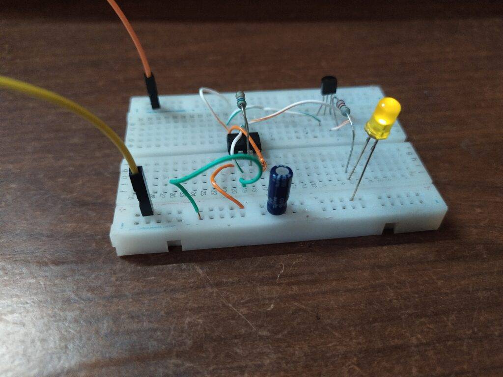
Now due to the increased current, the capacitor starts changing and at the same time the brightness of the LED also starts increasing slowly.
The output at pin 3 will change from high to low and vice-versa periodically. When the output is low the transistor goes off and the capacitor starts discharging.
The brightness of the LED will be going to reduce slowly and the cycle continues. You can also check our trending projects on IoT.

Components Required
| NE555 timer IC | |
| 220-ohm and 18K-ohm resistor | BUY LINK |
| multiple LEDs | BUY LINK |
| Connecting wires | BUY LINK |
| breadboard | BUY LINK |
| 9-volts battery | BUY LINK |
| 47 uF capacitor |
LED Brightness Control Circuit Diagram
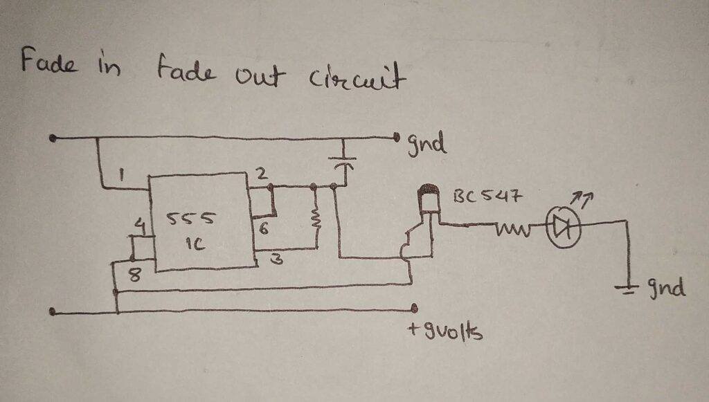
- Connect the positive rail of the breadboard with the 9-volt’s positive and negative with the negative rail.
- Then place the 555 timer ic on the middle of the breadboard as shown.
- Join pin 2 with pin 6 and pin 4 with pin 8 of the 555 timer ic.
- Now connect the base pin of the bc547 transistor with pin 6 of the ic.
- Attach the positive leg of the capacitor with pin 2 of the ic and the negative leg with the negative rail.
- Join pin 3 and pin 6 of the timer ic with each other via a 33K-ohm resistor.
- Connect pin 8 of the timer ic with the collector pin of the transistor.
- Now take an LED and connect its positive leg with the emitter pin of the transistor via a 220-ohm resistor and the negative leg with the negative rail of the breadboard.
- Attach pin 1 of the ic to the negative rail and pin 8 of the ic to the positive rail.

Complete the circuit and connect the power, the LED starts turning on and off slowly which is known as the breathing effect. If you like this project then also check Arduino tutorials and Raspberry Pi tutorials uploaded by us. Feel free to ask doubts in the comments section below also try to make this project by yourself.
HAPPY LEARNING!
Latest 555 timer projects
555 Timer LED Flasher | LED Flasher 555 Timer IC
Cell Phone Signal Jammer Using 555 IC | 555 timer project signal jammer
Fastest Finger First Circuit Using 555 timer IC

HEllo
Wwhere can I find you?