Hello guys. Welcome back to Techatronic. This tutorial will show you how to connect an Arduino board to a NodeMCU ESP8266 wirelessly using the NRF24L01 transceiver module. Thingspeak Server will receive the received data and upload it. This project is NRF24L01 Wifi Gateway with Arduino NRF24L01.
Although NodeMCU allows us to monitor data globally, the NRF24L01 is limited to receiving data up to a 100-meter range. The NRF24L01 interface, which can interface with an Arduino or NodeMCU ESP8266 microcontroller board, makes up the sensor node.
In my case, a NodeMCU board is being used to create a sensor node circuit. The data from the sensors will be transmitted from the sensor node to the gateway via the NRF24L01 transceiver module. Here, I’m giving a simple demonstration with the DHT11 Humidity & Temperature Sensor.As a result, we will send Gateway the temperature and humidity data.
At the receiving end, we intend to interface the NodeMCU ESP8266-12E Board with the NRF24L01 transceiver module. The receiver, also referred to as the gateway, is this. The Gateway has the ability to connect to a WiFi network.
The gateway wirelessly receives temperature and humidity data via the NRF24L01 transceiver module. The gateway will now upload the temperature and humidity value to the Thingspeak server.
Table of Contents
Components Required
| Arduino Uno | BUY LINK |
| NodeMCU ESP8266 Board | BUY LINK |
| NRF24L01 | BUY LINK |
| DHT11 Sensor | BUY LINK |
| Jumper Wires | BUY LINK |
| Breadboard | BUY LINK |
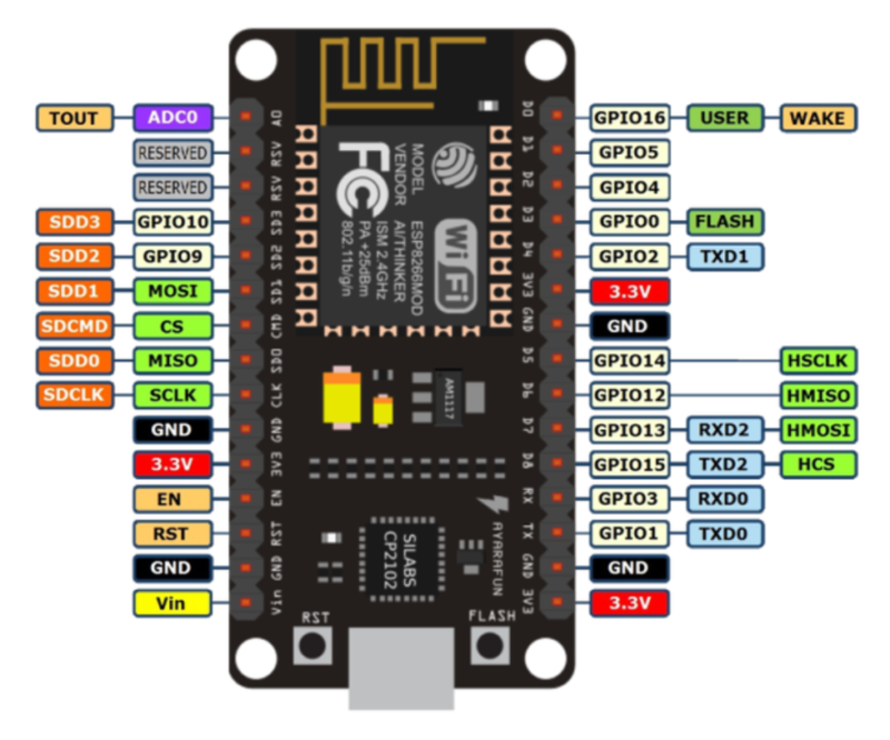
NodeMCU ESP8266
Espressif Systems manufactures the ESP8266, a system-on-a-chip (SOC) Wi-Fi microchip for Internet of Things (IoT) applications. The ESP8266 is now widely used in many Internet of Things devices due to its low cost, small size, and versatility with embedded devices.
IoT developers and manufacturers continue to favor the ESP8266 microcontroller chip, despite the ESP32 microcontroller chip’s recent advancement.Microcontrollers can connect to IEEE 802.11 bgn-enabled 2.4 GHz Wi-Fi by means of the ESP8266 module.
It can be used as a self-sufficient MCU by running an RTOS-based SDK, or it can be used with ESP-AT firmware to provide Wi-Fi connectivity to external host MCUs. The module reads, writes, and controls GPIOs in addition to having a complete TCP/IP stack.
Some Common Use Functions
The ESP8266 has a wide range of Internet of Things applications. The following are just a few of the uses for the chip:
- Data Processing: includes processing basic inputs from analog and digital sensors using an RTOS or Non-OS SDK in order to perform far more complex calculations.
- Networking: The Wi-Fi antenna on the module makes it possible for embedded devices to communicate with routers and send data.
- P2P Connectivity: Use IoT P2P connectivity to establish direct communication between ESPs and other devices.
- Web Server: Access pages created using development languages or HTML.
ESP8266 Applications
ESP8266 modules are frequently seen in the following Internet of Things devices:
- Smart locks and surveillance cameras are examples of smart security equipment.
- Intelligent machinery, such as PLCs (programmable logic controllers).
- Smart energy appliances, such as thermostats and HVAC systems.
- Wearable health monitors are among the smart medical devices
NRF24L01
The M177 NRF24L01 Wireless Module is this one. For the 2.4GHz ISM (Industrial, Scientific, and Medical) band, the nRF24L01 is a highly integrated, ultra-low power (ULP) 2Mbps RF transceiver integrated circuit.
With its sub-μA power down mode, advanced power management, peak RX/TX currents of less than 14mA, and a supply range of 1.9 to 3.6V, the nRF24L01 offers a true ULP solution that can last months or even years on coin cells or AA/AAA batteries.
The Arduino hobbyists are big fans of these RF modules. Many different applications that call for wireless control use the nRF24L01 wireless module. Since each module is a transceiver, it has the ability to send and receive data.
Circuit Diagram for Wifi Gateway with Arduino NRF24L01
In this case, two circuit assemblies are required for wireless communication. The Node Circuit is the first circuit, and the Gateway Circuit is the second. Any microcontroller can be used to create the Node Circuit, which is not dependent on a WiFi connection. Either an Arduino board or a NodeMCU ESP8266 can be used.
The Gateway Receiver Circuit, which requires a WiFi connection, is the second circuit. Thus, NodeMCU ESP8266 Board is required.
Transmitter Circuit: NRF24L01 Arduino/ESP8266 Node
Put together the transmitter circuit as the figure below illustrates. It includes a DHT11 sensor, an Arduino Uno, and an RF24L01.
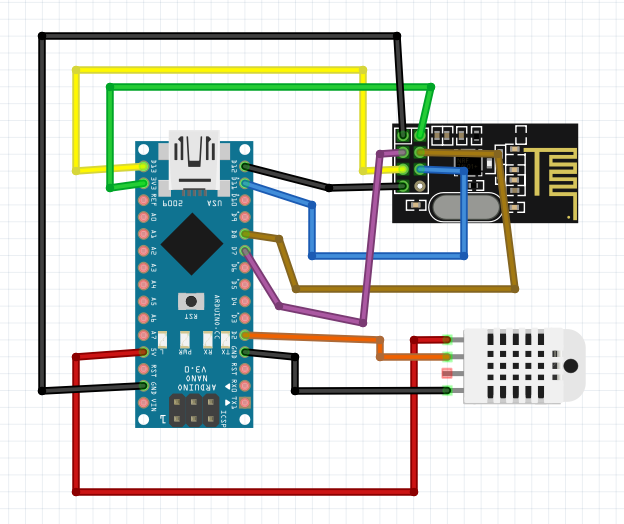
This is the connection between the NRF24L01 pins and the NodeMCU ESP8266 board:
MISO connects to pin D6 of the NodeMCU
MOSI connects to pin D7 of the NodeMCU
SCK connects to pin D5 of the NodeMCU
CE connects to pin D4 of the NodeMCU
CSN connects to pin D2 of the NodeMCU
GND and VCC of the NRF24L01 are connected to GND and 3.3V of the NodeMCU
The NodeMCU’s D1 pin is connected to the DHT11 Humidity & Temperature Sensor. Attach VCC and GND to the 3.3V and GND pins of the NodeMCU.
Receiver Circuit: NRF24L01 ESP8266 Gateway
As illustrated in the figure below, assemble the receiver circuit. It is composed of the nRF24L01 Module and the Nodemcu ESP8266 Board.
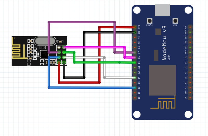
Here is a The NRF24L01 pins Connection with NodeMCU ESP8266 Board:
MISO connects to pin D6 of the NodeMCU
MOSI connects to pin D7 of the NodeMCU
SCK connects to pin D5 of the NodeMCU
CE connects to pin D4 of the NodeMCU
CSN connects to pin D2 of the NodeMCU
GND and VCC of the NRF24L01 are connected to GND and 3.3V of the NodeMCU
Setup Thingspeak
Setting up the Thingspeak account is now necessary. To configure Thingspeak, take the following actions:

Step 1: Visit https://thingspeak.com/ and create your account.
Step 2: Click “Channel” to create a new channel, then fill out the information below as it appears in the image.

Step 3: The “Write API Key” will appear when you click on the API Key. Take a copy of the API Key. This is crucial because the Code Part will need it.
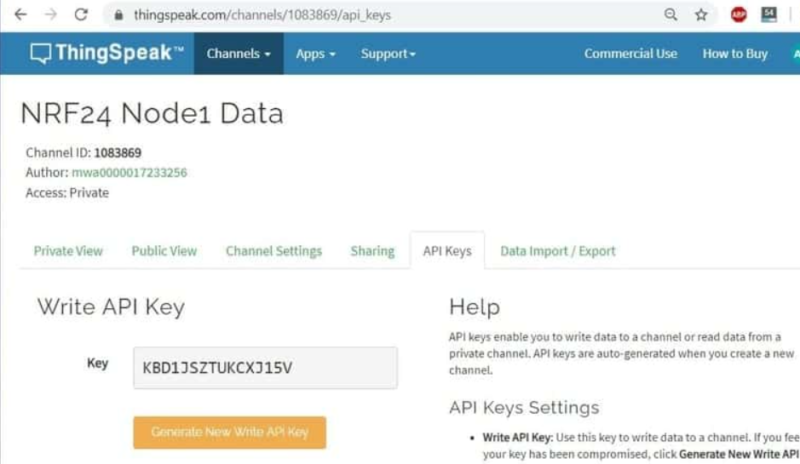
Step 4: By selecting “Private View,” you can alter the display window to your preference.
Code for NRF24L01 Wifi Gateway with Arduino
Code for Creating a Distinct Gateway and Node ID
We can use the following code to store the value in the EEPROM so that every node and gateway has a unique address. The EEPROM can withstand approximately 100,000 erases and writes.
To give each Gateway and Node a unique ID, copy and upload the code below. Since the data ID is stored in EEPROM, it will remain intact even if another code is uploaded to the board.
#include <EEPROM.h>
int deviceID = 0, curDeviceID;
void setup() {
  Serial.begin(9600);
  EEPROM.write(0, deviceID);
  curDeviceID = EEPROM.read(0);
  if (curDeviceID == deviceID) {
    Serial.print("Arduino ID successfully changed to: ");
    Serial.println(curDeviceID);
  }
}
void loop() {
  // put your main code here, to run repeatedly:
}
Arduino/ESP8266 NRF24L01 Node Code
Change these lines by commenting or uncommenting if you are not using a NodeMCU Board and are instead using an Arduino Nano.
#include <RH_NRF24.h>
#include "DHT.h"
#include <EEPROM.h>

 RH_NRF24 nrf24(2, 4); // use this for NodeMCU Amica/AdaFruit Huzzah ESP8266 Feather
 // RH_NRF24 nrf24(8, 7); // use this with Arduino UNO/Nano

#define DHTPIN D1
//#define DHTPIN 2

#define DHTTYPE DHT11
DHT dht(DHTPIN, DHTTYPE);

int deviceID = EEPROM.read(0);
int humidity, temperature;

void setup()
{
  Serial.begin(115200);
   dht.begin();
  while (!Serial)
    ; // wait for serial port to connect. Needed for Leonardo only
  if (!nrf24.init())
  {
    Serial.println("init failed");

  }
  // Defaults after init are 2.402 GHz (channel 2), 2Mbps, 0dBm
  if (!nrf24.setChannel(3))
  {
    Serial.println("setChannel failed");
  }
  if (!nrf24.setRF(RH_NRF24::DataRate2Mbps, RH_NRF24::TransmitPower0dBm)) {
    Serial.println("setRF failed");
  }
  Serial.println("Transmitter started");
}

void loop()
  {
  humidity = dht.readHumidity();
  temperature = dht.readTemperature();
  if (isnan(humidity) || isnan(temperature))
  {
    Serial.println(F("Failed to read from DHT sensor!"));
    return;
  }

  Serial.println("Sending to gateway");
  uint8_t data[4];

  data[0] = humidity;
  data[1] = temperature;
  data[2] = deviceID;

  Serial.println("------------- Measurements -------------");
  Serial.print("Humidity: ");
  Serial.print(data[0]);

  Serial.print(", Temperature: ");
  Serial.print(data[1]);

  Serial.print(", ID: ");
  Serial.print(data[2]);
  Serial.println();

  nrf24.send(data, sizeof(data));
  nrf24.waitPacketSent();

  // Now wait for a reply
  uint8_t buf[RH_NRF24_MAX_MESSAGE_LEN];
  uint8_t len = sizeof(buf);

  if (nrf24.waitAvailableTimeout(1000))
  {
    // Should be a reply message for us now
    if (nrf24.recv(buf, &len))
    {

      Serial.print("got reply: ");
      Serial.println((char*)buf);
    }
    else
    {

      Serial.println("recv failed");
    }
  }
  else
  {
    Serial.println("No reply.");

  }
  delay(5000);
}
ESP8266 NRF24L01 Gateway Code
Make changes to the Wifi SSID & Password as well as “Thingspeak API Key“.
#include <RH_NRF24.h>
#include <EEPROM.h>
#include <ESP8266WiFi.h>

String apiKey = "KBD1JSZTUKCXJ15V";

const char* ssid = "Alexahome";
const char* password = "loranthus";

WiFiClient client;
int gatewayID = EEPROM.read(0);

const char* server = "api.thingspeak.com";

RH_NRF24 nrf24(2, 4); // use this for NodeMCU Amica/AdaFruit Huzzah ESP8266 Feather

void setup()
{
  Serial.begin(115200);
  Serial.print("Receiver Started, ID: ");
  Serial.print("Connecting to ");
  Serial.println(ssid);
  Serial.print(gatewayID);
  Serial.println();
  WiFi.begin(ssid, password);
  while (WiFi.status() != WL_CONNECTED)
  {
    delay(500);
    Serial.print(".");
  }
  Serial.println("");
  Serial.println("WiFi connected");
  nrf24.init();
  nrf24.setChannel(3);
  nrf24.setRF(RH_NRF24::DataRate2Mbps, RH_NRF24::TransmitPower0dBm);
}

void loop()
{
  if (nrf24.available())
  {
    // Should be a message for us now
    uint8_t buf[RH_NRF24_MAX_MESSAGE_LEN];
    uint8_t len = sizeof(buf);
    if (nrf24.recv(buf, &len))
    {

      // Send a reply
      uint8_t sdata[] = "Data Received.";
      nrf24.send(sdata, sizeof(sdata));
      nrf24.waitPacketSent();

      int humidity = buf[0];
      int temperature = buf[1];
      int deviceID = buf[2];

      Serial.println("--- Data retrieved from device ---");
      if (client.connect(server, 80)) { // "184.106.153.149" or api.thingspeak.com
        String postStr = apiKey;
        postStr += "&field1=";
        postStr += String(temperature);
        postStr += "&field2=";
        postStr += String(humidity);
        postStr += "&field3=";
        postStr += String(gatewayID);
        postStr += "&field4=";
        postStr += String(deviceID);
        postStr += "\r\n\r\n";

        client.print("POST /update HTTP/1.1\n");
        client.print("Host: api.thingspeak.com\n");
        client.print("Connection: close\n");
        client.print("X-THINGSPEAKAPIKEY: " + apiKey + "\n");
        client.print("Content-Type: application/x-www-form-urlencoded\n");
        client.print("Content-Length: ");
        client.print(postStr.length());
        client.print("\n\n");
        client.print(postStr);

        Serial.println("---- Data sent to Thingspeak ----");
        Serial.print("Device ID: ");
        Serial.print(deviceID);
        Serial.print(", Temperature:");
        Serial.print(temperature);
        Serial.print(", Humidity:");
        Serial.println(humidity);
      }
      delay(1000);
      client.stop();
    }
  }
  else
  {

    //Serial.print("No New Message");
  }
//delay(15000);
}
I have assembled the whole circuit on a breadboard. As you know breadboard assembly is not effective for this type of project. So, PCBWay offers Rapid PCB Prototyping for Your Research Work. I personally, recommend PCBWay because you can get your first-try boards right in 24 hours!

The prototyping stage is the most critical period of time for engineers, students, and hobbyists. PCBWay not only makes your boards quick but also makes your job right as well as cost-effective. This greatly reduces your cost and shortens the time for developing your electronic
PCBWay can provide 2 Layer PCBs to highly advanced HDI and flex boards. Even though the PCBs they produce differ a lot regarding functionality and areas of use. I am impressed with the quality of the boards, the delivery time, and the cost-effectiveness
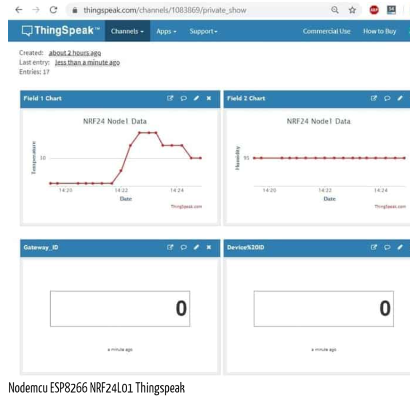
Keeping an eye on Thingspeak Server data
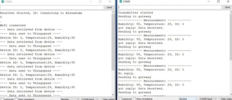
Once the code has been uploaded to both boards, you can access the Serial Monitor on both ports. If the device is working and the wiring connections are correct, Serial Monitor will show the following data.
Right now, you can access the Private View by opening your “Thingspeak Account.” Every 15 seconds, the data will be uploaded to the Thingspeak server.