
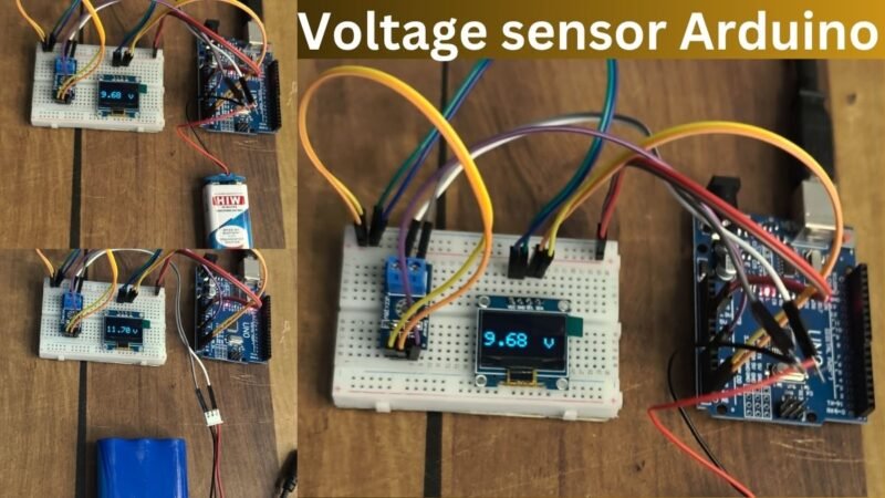
Hey guys. welcome back to the Techatronic. In this tutorial we are going to interface a very useful and unique sensor which is Voltage sensor. Interface Voltage sensor with Arduino Uno can help us in many projects where we need to monitor the battery voltage and power supply voltage. That’s why we have made this activity tutorial. The voltage sensor is very common sensor and very easy to use. only we need to connect the sensor to the Arduino analog input.
Table of Contents
Introduction
Voltage sensor having a voltage divider circuit to measure the voltage. and we can measure here voltage upto 25 DC Voltage. This sensor is easily connect to the programmer. Also, we are going to display the voltage reading to the OLED display so, the part of the OLED display also have included. we have made many tutorial on how to oled connected to the Arduino.
If you have to write on the OLED display. just learn and apply the method to the project and you will find the right way. Voltage detection or measurement basically done by many method but voltage divider is one of the most common method to measure the voltage. So , this sensor consist a voltage divider circuit inside it. voltage sensor is very useful in many project where we are using battery.

So it can measure the battery voltage and we can notified that our battery is not sufficiently charge. it is very beneficial in solar charger, EV bikes, car and other products and project. so, we have made this very simple tutorial so you can easily interface this voltage sensor with the project.
So, in this article i am gonna show you how to connect the sensor and how to code the voltage sensor. First of all i would like to mention the required components. then how to connect them and last but not the least how to do the code. We have many projects in which we have used this voltage sensor. so, here you have a chance to learn how to interface Interface Voltage sensor with Arduino Uno.
Required components
Arduino Uno
Voltage Sensor
Breadboard
Jumper wire
OLED Display
| Components | Link |
| Arduino Uno | Buy Link |
| Voltage Sensor | Buy Link |
| Breadboard | Buy Link |
| Jumper Wire | Buy Link |
| OLED Display | Buy Link |
Arduino Uno :-
Arduino is a microcontroller development report which is used widely in the field of Robotics electronics and iot so we are using this microcontroller development board which have 14 general input output pins 6 analogue pins also it’s supports I tolc SBI serial can all the Communication protocols. So it is very easy to Interface any sensor with this development board. So where using our voltage sensor with arduino Uno in this article which share all the detail how we can connect our sensor with this arduino uno. We have made a lot of project on arduino no as you can see in our website home page there is a category called you Arduino project or Arduino tutorial so you can get their all the information for Arduino.
Voltage Sensor:-
voltage sensor basically a device which can measure or detect the voltage from any source. So basically this voltage sensor use the voltage divider circuit inside it and it can measure the voltage up to 25 volt dc. So where using this voltage sensor in this project to get the voltage measurement from my all the device or all the projects batteries and other power sources.
OLED Display:-
Oled display stand for Organic light emitting diode display. So this display basically a very small display which can display the voltage or current which we are measuring in this project. So basically this display is using to monitor or displaying the voltage from the different sources with the help of voltage sensor and arduino. I do you know get the information for the voltage sensor and send this in information to the OLED display.

So now after getting all the information we have to make the circuit diagram which is very easy so here we have to connect our voltage sensor without know and oled it display with I don’t know so we are going to use some jumper wire braid board. Now we need a circuit diagram which can clearly show us how to connect all the material with each other. Here oled display supports the i2c communication. In which the SDA and SCL pin of Arduino will engage.
Voltage Sensor with Arduino Circuit Diagram.

You can see the above Circuit in which the connections are given below.
Connect OLED Vcc and Gnd with the Arduino Vcc and Gnd respectively.
Connect OLED SDA & SCK with Arduino A4, A5 respectively
Connect Voltage Sensor Vcc & Gnd with the Arduino Vcc & Gnd Respectively
Connect Voltage sensor Signal pin to the Arduino A0 pin.
We have complete all the information till the connections we have shared the circuit diagram also we have shared the connection table and above we have shared the component required so now the things remaining are the code and how to upload the code. So we will give the code to in this article so all can easily make this circuit Run.
Voltage Sensor with Arduino Code
#include <SPI.h>
 #include <Wire.h>
 #include <Adafruit_GFX.h>
 #include <Adafruit_SSD1306.h>
 #define screen_width 128 // OLED display width, in pixels
 #define screen_height 64 // OLED display height, in pixels
 #define OLED_RESET 4
 Adafruit_SSD1306 display(screen_width, screen_height);
#include <Q2HX711.h>

const byte hx711_data_pin = 3;
const byte hx711_clock_pin = 4;

Q2HX711 hx711(hx711_data_pin, hx711_clock_pin);
#include <SoftwareSerial.h>

#include <TinyGPS.h>

/* This sample code demonstrates the normal use of a TinyGPS object.
   It requires the use of SoftwareSerial, and assumes that you have a
   4800-baud serial GPS device hooked up on pins 4(rx) and 3(tx).
*/

TinyGPS gps;
SoftwareSerial ss(10, 11);


void setup() {
  // put your setup code here, to run once:
pinMode(A0, INPUT);
pinMode(2, INPUT_PULLUP);
Serial.begin(9600);
ss.begin(9600);
display.begin(SSD1306_SWITCHCAPVCC, 0x3C);
}

void loop() {


  bool newData = false;
  unsigned long chars;
  unsigned short sentences, failed;
  // put your main code here, to run repeatedly:
float m = analogRead(A0);
float n = (m*5)/200;
int d = digitalRead(2);


int X = hx711.read();

if(d==1)

{

display.clearDisplay();
 display.setTextSize(2);
 display.setTextColor(SSD1306_WHITE);
display.setCursor(0, 30);
 display.print("Accident");
 display.display();
 delay(200);

for (unsigned long start = millis(); millis() - start < 1000;)
  {
    while (ss.available())
    {
      char c = ss.read();
      // Serial.write(c); // uncomment this line if you want to see the GPS data flowing
      if (gps.encode(c)) // Did a new valid sentence come in?
        newData = true;
    }
  }

  if (newData)
  {
    float flat, flon;
    unsigned long age;
    gps.f_get_position(&flat, &flon, &age);
    Serial.print("LAT=");
    Serial.print(flat == TinyGPS::GPS_INVALID_F_ANGLE ? 0.0 : flat, 6);
    Serial.print(" LON=");
    Serial.print(flon == TinyGPS::GPS_INVALID_F_ANGLE ? 0.0 : flon, 6);
    Serial.print(" SAT=");
    Serial.print(gps.satellites() == TinyGPS::GPS_INVALID_SATELLITES ? 0 : gps.satellites());
    Serial.print(" PREC=");
    Serial.print(gps.hdop() == TinyGPS::GPS_INVALID_HDOP ? 0 : gps.hdop());
  }


}
//voltage sensor with Arduino
Serial.print(d);
Serial.print(".   ");
Serial.print(n);
Serial.print(".   ");
Serial.println(X);
delay(100);

 display.clearDisplay();
 display.setTextSize(2);
 display.setTextColor(SSD1306_WHITE);

display.setCursor(0, 0);
 display.print(X);
 display.setCursor(100, 0);
  display.setCursor(0, 30);
 display.print("No Worry");


 display.setCursor(0, 50);
 display.print(n);
 display.setCursor(100, 50);
 display.print("V");

 display.display();
 delay(100);


}
I have assembled the whole circuit on a breadboard. As you know breadboard assembly is not effective for this type of project. So, PCBWay offers Rapid PCB Prototyping for Your Research Work. I personally, recommend PCBWay because you can get your first-try boards right in 24 hours!
The prototyping stage is the most critical period of time for engineers, students, and hobbyists. PCBWay not only makes your boards quick but also makes your job right as well as cost-effective. This greatly reduces your cost and shortens the time for developing your electronic
PCBWay can provide 2 Layer PCBs to highly advanced HDI and flex boards. Even though the PCBs they produce differ a lot regarding functionality and areas of use. I am impressed with the quality of the boards, the delivery time, and the cost-effectiveness
Now, you need to upload the code into the Arduino using Arduino IDE. First you need to downnload the Arduino ide. We have uploaded the article in which we have shared how to upload the code into the arduino with the use of Arduino IDE. here we have also share how to interface voltage sensor with arduino. So we have shared all the detail from the required component to how to write the go so if you have still any doubt you can ask us in the comment section and if you like this post you can share this with your friends.
After completing the circuit and code in this voltage sensor with Arduino Article. now you have a one question how we can measure the voltage with this voltage sensor so here we have two port at the output site of the sensor so you have to connect to wire there and these two wires can help you to measure the voltage one wire should be connect to the positive terminal and other wire should be connect to the negative terminal so how it can be used to measure the voltage.