
Today we are going to make a colour sorting machine using arduino and TCS 3200. The colour sorting machine Project is very unique and useful project. So we are going to share all the detail about this project how does it work and how can we made it. If you want to learn or make this colour sorting machine project you need to read full article because we are sharing all the details here. Such as code circuit diagram and each and every steps to make. The colour sorting machine Project is very famous product in the industrial purposes. So we are going to make this project with the help of wooden material and mechanical tools and materials.
There are many there are many projects using colour sensor. But this time we are making a colour sorting machine to differentiate the material like we are differentiating the different colour boxes using colour sensor in this machine having a conveyor belt which carry all the boxes and the conveyor belt also attached a colour sensor.
Which continuously object and its colour so according to the colour belt conve y or carry the product to the end of the machine where machine attached with container so that right colour parcel will be entertained by the right container. Such as if the parcel is blue colour the parcel will be collected by the blue colour container. So the sensor works on this principle.
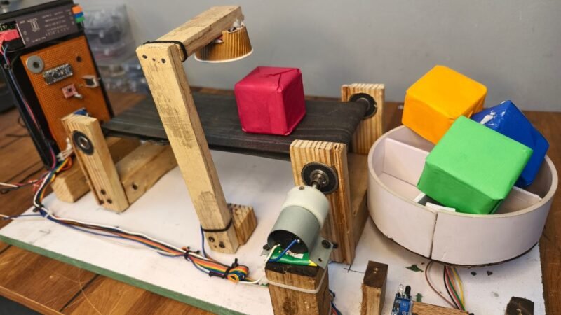
There are three blocks in this project first is power supply and PCB block second is conveyor belt and the third is container.
Power supply and PC blocks
This is the first block of this project there we have attached power supply of 12 volt and 5 ampere and a circuit board which we have made for this project. In this circuit board where using arduino Nano stepper driver a4988 and bug converter which are using to step down the voltage. And a MOSFET tip 122 which will be control the DC motor. On-Off switch.
PCB control board block were using a 12 volt 5 ampere power supply which is the regulated power supply which give us DC voltage and from this power supply output we have connect the stepper driver stepper motor and DC motor because all these things required 12 voltage now from the step down voltage which we are getting from the bug converter we have to connect sensors like where using all these things will work on 5 voltage so we can get 5 voltage from this work converter
Conveyor Belt Block
Conveyor Belt block in The colour sorting machine Project is made by the totally mechanical structure. Hindi conveyor belt block there is a DC motor which is responsible for rotating the conveyor belt conveyor belt is set up on two iron rod which are connected with the ball bearing on the both ends. When the DC motor get power than the motor start to rotate and also it rotate the iron rod which are connected through the conveyor belt.
There were using a height of motor with low RPM nearly 30 RPM nearly 60 RPM. The motor is gear motor which have more talk and less speed so that it can easily rotate the police and conveyor belt there we have made a mechanical structure which can easily control the conveyor belt by using a DC gear motor so we have shared all the detail how can we made this conveyor belt with the help of wooden wearing and mechanical structure also we have made a full video tutorial on YouTube where you can get all the details and all the steps which can help you to make this project by yourself.
Container Block.
In this container block we have a container with four different container inside it so V named all the container differently as colours first is red then green then yellow and then Blue. This big container is connected over a stepper motor which is control by the arduino and there is IR sensor which can help us to get the initial position of the container mounted over a stepper motor will decide to rotate for different colour boxes. For example if there is a box of blue colour then the stepper motor rotate a certain degree which are associated with the blue colour block. Green yellow and red.
If you want to make this project we are giving all the components details for The colour sorting machine Project here.
- Mechanical Material
- Tools
- Electronics Hardware
- Software required
- Mechanical Material
Iron Rod
Wooden
Ball bearing
Screws
Conveyor Belt
- Tools
Drill Machine
Hammer
Cutter
Paper cutter
Plier
Required Electronic Hardware for Colour Sorting Machine Project
You can buy all components are together-BUY LINK
| Arduino Nano | Buy Link |
| Stepper Driver A4988 | BUY LINK |
| Buck converter | BUY LINK |
| TIP122 | BUY LINK |
| On- off switch | BUY LINK |
| IR Sensor | BUY LINK |
| Nema 17 stepper motor | BUY LINK |
| 12V DC Geared Motor | BUY LINK |
| TCS3200 | BUY LINK |
| PCB Boards | BUY LINK |
Arduino Nano:- Arduino Nano is a microcontroller development board having atmega16 controller. Arduino have 13 digital input output pins, 8 Analog Pins and pwm pins. it supports Serial communication, I2C Communication, SPI communication protocols. In this project Arduino nano working as a brain which getting input from the TCS 3200 and IR sensor and operate dc motor, Stepper motor on it’s output ports.
Stepper Driver A4988:- Stepper Driver a4988 is used to control the stepper motor. without the a4988 the stepper motor can’t work. Stepper motor can’t run directly on the Arduino. so, we need to use this driver.
Buck Converter:- Buck converter or step down voltage device is help to maintain variable voltage as per our requirement. there is a potentiometer which can control the voltage when we rotate the potentiometer.there is switching of input voltage in buck converter through the inductor. which store the power as magnetic field.then it release the energy to the load.
TIP122 :- TIP 122 is a MOSFET which can control the DC current. the mosfet is work as a switch here. when external voltage applied on the gate terninal then the source and drain start conducting the electricity. we use this mosfet as a switch to control the DC motor in this colour sorting machine Project.
IR Sensor :- IR sensor also known as the infrared sensor. which transmit the Infrared light and receive by the receiver. if there is an object infront of the sensor then the receiver get the tranmistted light and turn the signal on. so it helps in this project to find the initial position of stepper motor.
Nema 17 stepper motor:- Nema 17 stepper motor have high precision and high torque in this range of stepper motor thats why we are using this motor in this project. Stepper motor always rotate in steps that’s why they are called as stepper motors.
TCS3200:- TCS3200 colour sensor is most knowing colous sensor in the sensor industry. we have made a alot of project on this sensor also our this Colour sorting machine project we are using tcs3200 sensor. There are 4 led which transmiot the white light to the object. object may have any colour. for example we have a red colour object. The colour object that wavelenghth. and the receiver doesn’t receive the colour spectrum by this The colour sorting machine Project the sensor get to know the colour of the object.
Now, we need a circuit diagram.
Colour Sorting Machine Project Circuit Diagram

Connect All the components according to the Circuit Diagram.
Connect 12V , 5 AMP power supply +wire with the Buck converter +terminal.
Connect 12V , 5 AMP power supply -wire with the Buck converter -terminal.
Connect Arduino 2, 3 pin with the A4988 DIR and STEP pins respectively
Connect Arduino 4, 5, 6 ,7 pin to the TCS3200 S1, S0, S3, S2 pins Respectively
Connect Arduino 8 pin to the TCS3200 out pins Respectively
Connect Vcc & Gnd Pin from TCS 3200 with Arduino 5V & Gnd pin
Connect RST and SLP pin together in A4988
Connect IR input pin to the Pin 11 of Arduino
Connect IR sensor Vcc & Gnd pin to the Arduino Vcc and Gnd pin
Connect A4988 Vdd & Ground pin to the Arduino 5v and Ground Pin.
Connect A4988 A,B,C,D pin to the Stepper motor coil pins
Connect a 100 mf Capacitop to the input voltage pin of A4988
Connect Arduino pin 12 to the TIP 122 terminal 1
Tip 122 terminal 2 will be connect to the Dc motor pin
Tip 122 Terminal 3 will be connect to Gnd pin of Buck Converter.
Dc geared motor + wire connect to the Buck converter + pin input.
Colour Sorting Machine Project Arduino Code
/*
 * Simple demo, should work with any driver board
 *
 * Connect STEP, DIR as indicated
 *
 * Copyright (C)2015-2017 Laurentiu Badea
 *
 * This file may be redistributed under the terms of the MIT license.
 * A copy of this license has been included with this distribution in the file LICENSE.
 */
//techatronic.com
#include <Arduino.h>
#include "BasicStepperDriver.h"

// Motor steps per revolution. Most steppers are 200 steps or 1.8 degrees/step
#define MOTOR_STEPS 50
#define RPM 100

// Since microstepping is set externally, make sure this matches the selected mode
// If it doesn't, the motor will move at a different RPM than chosen
// 1=full step, 2=half step etc.
#define MICROSTEPS 1

// All the wires needed for full functionality
#define DIR 3
#define STEP 2
//Uncomment line to use enable/disable functionality
//#define SLEEP 13

// 2-wire basic config, microstepping is hardwired on the driver
BasicStepperDriver stepper(MOTOR_STEPS, DIR, STEP);

//Uncomment line to use enable/disable functionality
//BasicStepperDriver stepper(MOTOR_STEPS, DIR, STEP, SLEEP);
#define S0 4
#define S1 5
#define S2 6
#define S3 7
#define sensorOut 8

int r = 0;
int g = 0;
int b = 0;
void setup() {
    stepper.begin(RPM, MICROSTEPS);
    // if using enable/disable on ENABLE pin (active LOW) instead of SLEEP uncomment next line
    // stepper.setEnableActiveState(LOW);
    pinMode(11, INPUT_PULLUP);
    //pinMode(10, OUTPUT);
    Serial.begin(9600);
     pinMode(S0, OUTPUT);
  pinMode(S1, OUTPUT);
  pinMode(S2, OUTPUT);
  pinMode(S3, OUTPUT);
  pinMode(sensorOut, INPUT);
  pinMode(10, OUTPUT);
  // Set Pulse Width scaling to 20% colour sorting machine Project
  digitalWrite(S0, HIGH);
  digitalWrite(S1, LOW);
  // Enabl UART for Debugging
}

void loop() {
  int m = digitalRead(11);
  Serial.println(m);
  if(m==0)
  {
   stepper.stop();
     analogWrite(10, 230);

    delay(100);

   digitalWrite(S2,LOW);
  digitalWrite(S3,LOW);
  // Reading the output frequency The colour sorting machine Project
 r = pulseIn(sensorOut, LOW);
  // Printing the value on the serial monitor
  Serial.print("R= ");//printing name
  Serial.print(r);//printing RED color frequency
  Serial.print("  ");
  delay(300);

  // Setting Green filtered photodiodes to be read
  digitalWrite(S2,HIGH);
  digitalWrite(S3,HIGH);
  // Reading the output frequency
  g = pulseIn(sensorOut, LOW);
  // Printing the value on the serial monitor
  Serial.print("G= ");//printing name
  Serial.print(g);//printing RED color frequency
  Serial.print("  ");
  delay(300);

  // Setting Blue filtered photodiodes to be read
  digitalWrite(S2,LOW);
  digitalWrite(S3,HIGH);
  // Reading the output frequency
  b = pulseIn(sensorOut, LOW);
  // Printing the value on the serial monitor
  Serial.print("B= ");//printing name
  Serial.print(b);//printing RED color frequency
  Serial.println("  ");
  delay(300);
  if (r <= 600 && r>=380)
  {
    Serial.println("Colour Red");
  }
  else if (g<=800 && g>=510 )
  {
    Serial.println("Colour Green");
     stepper.rotate(450);


delay(4000);
  }
  else if (b <= 440 && b>=350)
  {
    Serial.println("Colour blue");
     stepper.rotate(1100);


delay(4000);
  }

  else if  (r <= 340 && r>=160)
  {
    Serial.println("Yellow Colour");
    stepper.rotate(800);


delay(4000);
  }

  else
  {
    Serial.println("NO Colour");
  }

  }


  else
  {

   stepper.rotate(10);

delay(10);
  //


}


  }
Upload this Code into your Arduino by using Arduino IDE. If you have any issue with the code upload you can refer our latest article – How to upload Code.
I have assembled the whole circuit on a breadboard. As you know breadboard assembly is not effective for this type of project. So, PCBWay offers Rapid PCB Prototyping for Your Research Work. I personally, recommend PCBWay because you can get your first-try boards right in 24 hours!

The prototyping stage is the most critical period of time for engineers, students, and hobbyists. PCBWay not only makes your boards quick but also makes your job right as well as cost-effective. This greatly reduces your cost and shortens the time for developing your electronic
PCBWay can provide 2 Layer PCBs to highly advanced HDI and flex boards. Even though the PCBs they produce differ a lot regarding functionality and areas of use. I am impressed with the quality of the boards, the delivery time, and the cost-effectiveness
Video Sample
If you guys have any doubt you can ask us in the comment section.