Table of Contents
Introduction
Hey guys, welcome back to Techatronic. Do you know what an audio equalizer is and what it is used for? Well if not then don’t worry we are here to help you. In this article, we are going to make an audio equalizer circuit using some basic components in this basic electronic project.
All the necessary information is given below for your convenience. Read the full article carefully and then try to make it on your own transistor project. These manual audio controls can be seen in MP3 players, home theaters, etc.
So we are trying to make the same manual controls using some basic components and also in a simpler way so that you can understand it. You can also read more articles on Arduino and IoT written by us.

Working of the Audio Equalizer / bass booster
You can call this circuit a bass booster or volume control circuit because the purpose of this circuit is that you can manually control the volume and the bass of the output audio signal.
You can play any song of your choice using an AUX cable. This circuit is only for volume and bass control. You can control the bass and volume by rotating the first and second potentiometer.

In this project, we are using an audio amplifier circuit too. If you already have a mini amplifier circuit and you want to use it then you can connect the input pins of the amplifier with the out pins of the circuit that we made.
We are using a simple audio amplifier circuit made by us.
Components Required

| 2 x 100K potentiometer | BUY LINK |
| 2 x Capacitor 0.1 uF | |
| Resistors 1K, 10K | BUY LINK |
| AUX cable | |
| Connecting wires | BUY LINK |
| breadboard | BUY LINK |
| Speaker |
Circuit Diagram for Audio Equalizer

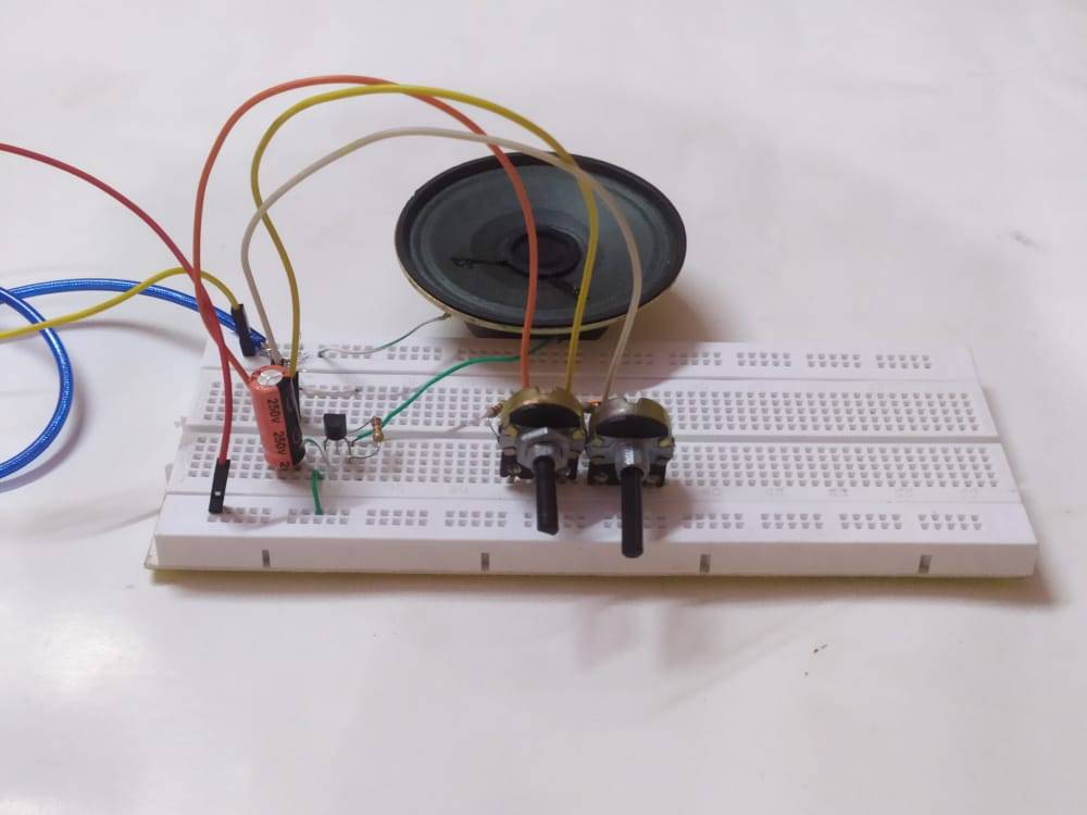
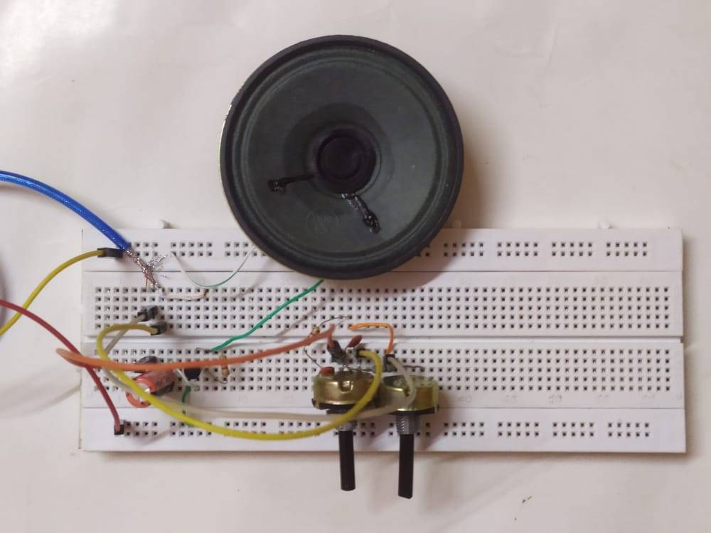
- Take two 100K potentiometers and place them on the breadboard.
- Then take a 0.1 uF capacitor and connect one leg with the first pin of the potentiometer and the other leg with the second pin of the same potentiometer.
- Place another 0.1 uF capacitor between the second and third pins of the first potentiometer as given in the transistor project circuit diagram.
- Now to the first pin of the first potentiometer connect a 10K resistor and join the other leg of the resistor with the first pin of the second potentiometer.
- Join the second pin of the first potentiometer with the third pin of the second potentiometer via a 1K resistor. Now take an AUX cable and cut its one end.
- Join the ground wire of the AUX with the first pin of the second potentiometer.
- Connect the signal (right) wire of the AUX cable with the third pin of the first potentiometer.
- Just make the amplifier circuit that is given in the diagram and connect it with this circuit as shown.
Your volume control circuit is now ready to use.
Let’s Test the Circuit

We hope you liked this audio equalizer circuit and if you have any doubts regarding this project then you can ping us in the comments section given below. For more on these topics check out our tutorials on Arduino and Raspberry Pi, and if you’re interested in making music, take a look at these 4 tips to get the most out of your drum machine. https://www.singularsound.com/blogs/news/4-beatbuddy-tips
Thanks for reading.