
The potentiometer Is also known as the variable resistance. In this activity, we are controlling led brightness with Arduino and potentiometer which have the option to change the resistance according to the requirement. in this post, we will share how to connect a potentiometer to Arduino tutorial. It is very important to learn because it will help you to interface with many analog sensors. if you know the basics of the hardware and it’s working then you can upgrade it by yourself. for example, if you do the Arduino potentiometer code then you can also write code for the flex sensor. there is two way to interface the sensor with the Arduino one is a digital connection and another is analog. digital output only gives 2 values high and low. so you can use this for a maximum of two conditions. for example, if the value is high light will be on and if the value is low the light will be off. but in the case of analog output, you have 0 to 1024 different values and there you can make more than 1000 conditions.
This experiment is only to learn you the basic fundamental of analog sensor interfacing. there are many students who struggle with the interface and the connection with the sensor. that’s why we are posting this potentiometer to Arduino article to teach them the right way to interface the sensor. because if you are making a project directly without the basics it will be difficult to make the project work. as you can see out sign language glove with a flex sensor which is also the variable resistance-based sensor. but if you have the basics you can connect any of the sensors easily. we observed that more than 80% of students don’t have the basics. we want you to learn and everything. Arduino pot connection is very easy but you need to extract the value and show it to the serial monitor. without a serial monitor, you can’t observe the potentiometer value. you will experience the live changes on the monitor with the potentiometer.
what is a potentiometer?
A potentiometer is a variable resistor which can adjust their resistivity manually. there are two types of potentiometer rotatory pot and a preset pot. as you can see in the given images.
These are used by their application. but mainly the Rotatory pot uses in the projects and products too.
How does the potentiometer works?
As I have mentioned above that the potentiometer is a variable resistor. variable means we can adjust the resistivity of the system. for example at one point you need 1k resistance and after sometimes you need 3k there. so you can’s change the resistance in the circuit frequently but in this case, you can adjust the resistance by the potentiometer you need to rotate the potentiometer pin. so potentiometer to Arduino tutorial is good to learn. and you will see the changes in the system. the potentiometer has the circular resistance material over the surface and a knob compress on the same material. the resistivity depends on the path completed by the knob over the resistor surface. for example, if you have traveled in a circular path you are completing the path like a knob over the surface. And this Will vary the value in Arduino Potentiometer value you can use this in any application.
Components Required
- Arduino UNO
- USB cable for uploading the code
- 10k Potentiometer
- LED
- 220-ohm resistor
- Jumper wires and a breadboard
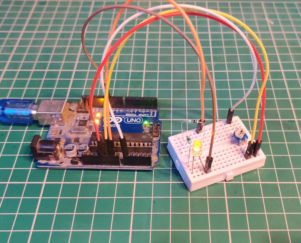
Arduino Potentiometer Wiring
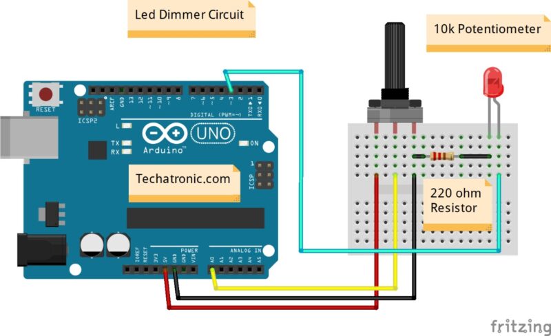
Wiring with the Potentiometer and Arduino is very simple there are only three wires in the Potentiometer. Positive, negative, and output. Connect Arduino 5v pin to the Potentiometer right pin and Arduino and pin connect to the potentiometer left pin. and output pin with the Arduino analog pin. Let see the controlling led brightness Arduino potentiometer connection in the given diagram.
| Arduino UNO | 10K Potentiometer | |
| ( +5V ) | Terminal 1 | |
| A0 Pin | Terminal 2 | |
| GND | Terminal 3 | |
| Arduino | LED R | 220 Ohm Resistor |
| D3 Pin | Anode Pin | |
| GND | Terminal 1 | |
| Cathode Pin | Terminal 2 |
I hope you will understand the wiring easily by the given circuit.
Now we will talk about the Arduino Potentiometer code
Arduino led fading with potentiometer code:-
 void setup()
 {
 Serial.begin(9600);
 pinMode(3,OUTPUT); // LED
 pinMode(A0,INPUT); // Potentiometer
 }
 void loop()
 {
 int s=analogRead(A0);
 int z=map(s,0,1024,0,255);
 Serial.println(z);
 analogWrite(3,z);
 }
The above setup is known as the void setup and in this setup all the instructions run only one time. and then it will go to another loop known and the main setup. where our code repeats continuously. we are storing the output value of the sensor into the variable s and then map the value with the 0 to 255. because PWM has the 0 to 255 value which comes under the 0 to 5v. which controls the brightness of the led.