

He is welcome back again this time we are making a fire fighting robot also we have made a firefighting robot earlier but this time we did some changes like earlier robot only runs on autonomously but this time we have added the wireless communication to which is bluetooth so we have added a Bluetooth module into this fire fighting robot.
With the help of this changes we can also control this robot boy phone. Because you know autonomous robot there is many errors. And each time it is not work well so we have decided to add the control feature which can be do with the mobile application. For now this this fire fighting robot can work accurately. So basically the fire fighting robot is the robot which help in the fire fighting if there is plane near to the robot it can detect and it can control it.
So in our previous robot we have only the autonomous mode we can’t control this robot so now we have added this feature so we can control it by our mobile phone to there is two mode. This two more can be switch by this mobile application so first of all we have to download this application which is BT car controller and then we have two pair with the Bluetooth of our device and then we can select the mode so the remote control mode is by default and if we want to work it in the autonomous mode we can do it by a button which is on the upper part of the application.
So this time we have both side autonomous and bluetooth control robot which can do a better job. fire fighting robot is a robot which extinguish the fire using water spraying. A fire fighting robot we have made earlier but this time we are making an advance fire fighter robot using bluetooth control. So to make a fire fighter robot we need some electronic components , software and tools. so, i will share all the detail.
Required Components
Arduino Nano
Components Required
| Arduino Uno | BUY LINK |
| flame IR Sensor | BUY LINK |
| Robot Chassis | BUY LINK |
| 12v Battery | BUY LINK |
| Jumper Wire | BUY LINK |
| Nozzle for water | BUY LINK |
| Water pump 5v | BUY LINK |
| Single channel relay | BUY LINK |
| Servo Motor | BUY LINK |
| Wheel4- | BUY LINK |
| Bo motor | BUY LINK |
| L298N Motor driver | BUY LINK |
| on off switch | BUY LINK |
| Bluetooth. HC-05 | BUY LINK |
Can you buy all components together-BUY LINK
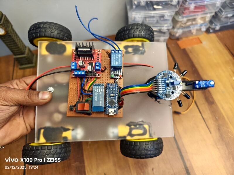
so, above we have share all the components which will required to make this amazing fire fighting robot. This robot can extinguish the Fire with the help of flame sensor detection. In this fire fighting robot we have added a new feature which is Bluetooth control so here we will control this robot from a mobile application which is called RC car controller. In the previous version we have not interface the acid 05 Bluetooth module with the robot so this time we have upgrade our previous robot with this new one so it is more accurate. More powerful and more efficient so if you are making the old one the fire fighting robot we will suggest you to see this one once. We shared our all project on instagram.
Till now we have shared what is this robot and how does it work and also we have share what component we required to make this amazing robot. So now the turn is to connect all the component together. And assemble all the material to make this fire fighting robot. If you have any problem in assemble the material and interface the component you can watch our video on YouTube the link is given below.
Now we required a circuit diagram for the reference which can help us to connect all the component together.
Fire fighting robot Circuit Diagram

This is the circuit diagram of the fire fighting robot which we have made with bluetooth control feature.
Arduino Nano Connections:
- All sensor and module inputs are connected to digital/analog pins of Arduino Nano.
- Power rails from Arduino (5V and GND) supply all modules.
2. Bluetooth Module (HC-05):
- VCC → 5V
- GND → GND
- TX → Arduino RX (D0)
- RX → Arduino TX (D1) (via voltage divider for 3.3V safe logic)
3. IR Obstacle Sensors (x4):
- Each has 3 wires: VCC, GND, and OUT
- VCC → 5V
- GND → GND
- OUT → Connected to 4 different Arduino digital pins
4. Servo Motor:
- Signal Pin → One of Arduino’s PWM pins
- VCC → 5V
- GND → GND
5. Relay Module:
- IN Pin → Digital pin of Arduino
- VCC → 5V
- GND → GND
- COM, NO, NC – Connected to an external power source and a device (light, pump, etc.)
6. L298N Motor Driver:
- Controls the 4 DC motors (2 channels with parallel motors)
- IN1, IN2, IN3, IN4 → 4 Arduino digital pins
- ENA, ENB – Either tied high or connected to PWM pins for speed control
- OUT1 to OUT4 → Connected to the 4 DC motors
- 12V Power → From 12V battery
- GND → Common ground with Arduino
- 5V Enable Jumper → Present (uses onboard regulator)
7. DC Motors:
- Connected via L298N motor driver
- Yellow & green wires are standard motor connections
8. Power Supply:
- A 12V battery powers the motor driver and Arduino
- A push button switch is used to turn the circuit on/off
- Red and black wires handle power and ground lines
Arduino Nano Pin Assignments:
| Component | Connected to Arduino Pin |
|---|---|
| Bluetooth TX (HC-05) | D0 (RX) |
| Bluetooth RX (HC-05) | D1 (TX via voltage divider) |
| IR Sensor 1 (Leftmost) | D2 |
| IR Sensor 2 | D3 |
| IR Sensor 3 | D4 |
| IR Sensor 4 (Rightmost) | D5 |
| Servo Motor Signal | D6 |
| Relay Module IN | D7 |
| Motor Driver IN1 | D8 |
| Motor Driver IN2 | D9 |
| Motor Driver IN3 | D10 |
| Motor Driver IN4 | D11 |
HC-05 Bluetooth Module
| Pin | Connect to |
|---|---|
| VCC | 5V on Arduino |
| GND | GND on Arduino |
| TX | D0 (RX) on Arduino |
| RX | D1 (TX via 1kΩ–2kΩ voltage divider) |
IR Sensors (x4)
Each sensor has 3 pins: VCC, GND, OUT
Connect all VCCs to 5V and all GNDs to GND
| Sensor | OUT pin to Arduino |
|---|---|
| IR1 | D2 |
| IR2 | D3 |
| IR3 | D4 |
| IR4 | D5 |
Servo Motor
| Pin | Connect to |
|---|---|
| Signal | D6 on Arduino |
| VCC | 5V |
| GND | GND |
Relay Module (1-Channel)
| Pin | Connect to |
|---|---|
| VCC | 5V on Arduino |
| GND | GND |
| IN | D7 on Arduino |
L298N Motor Driver Module
| Pin | Connect to |
|---|---|
| IN1 | D8 on Arduino |
| IN2 | D9 on Arduino |
| IN3 | D10 on Arduino |
| IN4 | D11 on Arduino |
| ENA | Jumpered (or to PWM) |
| ENB | Jumpered (or to PWM) |
| OUT1/OUT2 | Motor 1 (left side) |
| OUT3/OUT4 | Motor 2 (right side) |
| 12V | 9V Battery +ve |
| GND | Battery -ve & Arduino GND |
| 5V EN Jumper | Plugged in |
Now, we need a code to run this fire fighting Robot
Fire fighting Robot Code
#include <Servo.h>

Servo myservo;  // create servo object to control a servo
// twelve servo objects can be created on most boards

int pos = 0;
char m=0;
void setup() {
  // put your setup code here, to run once:
 myservo.attach(9);

pinMode(8, OUTPUT);  //WATER PUMP

pinMode(A0, INPUT_PULLUP);
pinMode(A1, INPUT_PULLUP);
pinMode(A2,INPUT_PULLUP);


pinMode(4, OUTPUT);
pinMode(5, OUTPUT);
pinMode(6, OUTPUT);
pinMode(7, OUTPUT);

pinMode(8, OUTPUT);

pinMode(10, OUTPUT);
//pinMode(9, OUTPUT);
Serial.begin(9600);


digitalWrite(8, LOW);
delay(80);
for (pos = 0; pos <= 60; pos += 1) { // goes from 0 degrees to 180 degrees
    // in steps of 1 degree
    myservo.write(pos);              // tell servo to go to position in variable 'pos'
    delay(15);                       // waits 15 ms for the servo to reach the position
  }
  for (pos = 60; pos >= 0; pos -= 1) { // goes from 180 degrees to 0 degrees
    myservo.write(pos);              // tell servo to go to position in variable 'pos'
    delay(15);                       // waits 15 ms for the servo to reach the position
  }

  analogWrite(3, 200);
}

void loop() {

if (Serial.available()>0)
 {
  m=Serial.read();
  Serial.println(m);
  }
 if (m=='S')
{


  // put your main code here, to run repeatedly:

int a = analogRead(A0);
int b = analogRead(A1);
int c = analogRead(A2);


Serial.print(a);
Serial.print("    ");
Serial.print(b);
Serial.print("    ");
Serial.print(c);
Serial.println("    ");

//delay(50);

if (a<100)

{


   analogWrite(10, 150);
analogWrite(3, 130);
digitalWrite(4, HIGH);
digitalWrite(5, LOW);
digitalWrite(6, HIGH);
digitalWrite(7, LOW);
  delay(200);


  digitalWrite(4, LOW);
  digitalWrite(5, LOW);
  digitalWrite(6, LOW);
  digitalWrite(7, LOW);

  digitalWrite(8, HIGH);
  delay(100);
  for (pos = 0; pos <= 60; pos += 1) { // goes from 0 degrees to 180 degrees
    // in steps of 1 degree
    myservo.write(pos);              // tell servo to go to position in variable 'pos'
    delay(15);                       // waits 15 ms for the servo to reach the position
  }
  for (pos = 60; pos >= 0; pos -= 1) { // goes from 180 degrees to 0 degrees
    myservo.write(pos);              // tell servo to go to position in variable 'pos'
    delay(15);                       // waits 15 ms for the servo to reach the position
  }

  //delay(200);
   digitalWrite(8, LOW);
  }


  else if(b<100)

{
analogWrite(10, 150);
analogWrite(3, 130);
digitalWrite(4, HIGH);
digitalWrite(5, LOW);
digitalWrite(6, HIGH);
digitalWrite(7, LOW);
  delay(200);
digitalWrite(4, LOW);
  digitalWrite(5, LOW);
  digitalWrite(6, LOW);
  digitalWrite(7, LOW);

  digitalWrite(8, HIGH);
  delay(100);
for (pos = 0; pos <= 60; pos += 1) { // goes from 0 degrees to 180 degrees
    // in steps of 1 degree
    myservo.write(pos);              // tell servo to go to position in variable 'pos'
    delay(15);                       // waits 15 ms for the servo to reach the position
  }
  for (pos = 60; pos >= 0; pos -= 1) { // goes from 180 degrees to 0 degrees
    myservo.write(pos);              // tell servo to go to position in variable 'pos'
    delay(15);                       // waits 15 ms for the servo to reach the position
  }
  for (pos = 0; pos <= 60; pos += 1) { // goes from 0 degrees to 180 degrees
    // in steps of 1 degree
    myservo.write(pos);              // tell servo to go to position in variable 'pos'
    delay(15);                       // waits 15 ms for the servo to reach the position
  }
  for (pos = 60; pos >= 0; pos -= 1) { // goes from 180 degrees to 0 degrees
    myservo.write(pos);              // tell servo to go to position in variable 'pos'
    delay(15);                       // waits 15 ms for the servo to reach the position
  }
   digitalWrite(8, LOW);
  }
  else if(c<=100)

{
analogWrite(10, 150);
analogWrite(3, 130);
digitalWrite(4, HIGH);
digitalWrite(5, LOW);
digitalWrite(6, HIGH);
digitalWrite(7, LOW);
  delay(200);
digitalWrite(4, LOW);
  digitalWrite(5, LOW);
  digitalWrite(6, LOW);
  digitalWrite(7, LOW);

  digitalWrite(8, HIGH);
  delay(100);
for (pos = 0; pos <= 60; pos += 1) { // goes from 0 degrees to 180 degrees
    // in steps of 1 degree
    myservo.write(pos);              // tell servo to go to position in variable 'pos'
    delay(15);                       // waits 15 ms for the servo to reach the position
  }
  for (pos = 60; pos >= 0; pos -= 1) { // goes from 180 degrees to 0 degrees
    myservo.write(pos);              // tell servo to go to position in variable 'pos'
    delay(15);                       // waits 15 ms for the servo to reach the position
  }
  for (pos = 0; pos <= 60; pos += 1) { // goes from 0 degrees to 180 degrees
    // in steps of 1 degree
    myservo.write(pos);              // tell servo to go to position in variable 'pos'
    delay(15);                       // waits 15 ms for the servo to reach the position
  }
  for (pos = 60; pos >= 0; pos -= 1) { // goes from 180 degrees to 0 degrees
    myservo.write(pos);              // tell servo to go to position in variable 'pos'
    delay(15);                       // waits 15 ms for the servo to reach the position
  }
   digitalWrite(8, LOW);

  }


else if(c<=700 && c>=110)

{

  digitalWrite(8, LOW);

analogWrite(3, 200);

digitalWrite(4, HIGH);
  digitalWrite(5, LOW);
  digitalWrite(6, LOW);
  digitalWrite(7, HIGH);


  delay(300);


analogWrite(3, 130);
digitalWrite(4, LOW);
digitalWrite(5, HIGH);
digitalWrite(6, LOW);
digitalWrite(7, HIGH);
  delay(200);

  }


else if(b<=700 && b>=110)

{


 digitalWrite(8, LOW);


  analogWrite(10, 150);
analogWrite(3, 130);
digitalWrite(4, LOW);
digitalWrite(5, HIGH);
digitalWrite(6, LOW);
digitalWrite(7, HIGH);
  delay(200);

  }

  else if(a<=700 && a>=110)

{
digitalWrite(8, LOW);
analogWrite(10, 180);
analogWrite(3, 200);

  digitalWrite(4, LOW);
  digitalWrite(5, HIGH);
  digitalWrite(6, HIGH);
  digitalWrite(7, LOW);


delay(300);
analogWrite(10, 150);
analogWrite(3, 130);

digitalWrite(4, LOW);
digitalWrite(5, HIGH);
digitalWrite(6, LOW);
digitalWrite(7, HIGH);
  delay(200);

  }

else

{

  analogWrite(10, 120);
analogWrite(3, 130);
digitalWrite(7, LOW);
digitalWrite(4, LOW);
digitalWrite(5, LOW);
digitalWrite(6, LOW);


  digitalWrite(8, LOW);
delay(10);


  }


}


else if(m=='V')
{
//
 analogWrite(10, 150);
analogWrite(3, 130);
digitalWrite(4, HIGH);
digitalWrite(5, LOW);
digitalWrite(6, HIGH);
digitalWrite(7, LOW);
  delay(200);


  digitalWrite(4, LOW);
  digitalWrite(5, LOW);
  digitalWrite(6, LOW);
  digitalWrite(7, LOW);

  digitalWrite(8, HIGH);
  delay(100);
  for (pos = 0; pos <= 60; pos += 1) { // goes from 0 degrees to 180 degrees
    // in steps of 1 degree
    myservo.write(pos);              // tell servo to go to position in variable 'pos'
    delay(15);                       // waits 15 ms for the servo to reach the position
  }
  for (pos = 60; pos >= 0; pos -= 1) { // goes from 180 degrees to 0 degrees
    myservo.write(pos);              // tell servo to go to position in variable 'pos'
    delay(15);                       // waits 15 ms for the servo to reach the position
  }

  //delay(200);
   digitalWrite(8, LOW);


//

}


else if (m=='F')
{
  analogWrite(10, 150);
analogWrite(3, 150);
digitalWrite(4, LOW);
digitalWrite(5, HIGH);
digitalWrite(6, LOW);
digitalWrite(7, HIGH);

  }


  else if (m=='B')
{
  analogWrite(10, 150);
analogWrite(3, 150);
digitalWrite(4, HIGH);
digitalWrite(5, LOW);
digitalWrite(6, HIGH);
digitalWrite(7, LOW);

  }


else if (m=='R')
{
   analogWrite(10, 180);
analogWrite(3, 200);

  digitalWrite(4, LOW);
  digitalWrite(5, HIGH);
  digitalWrite(6, HIGH);
  digitalWrite(7, LOW);

  }

  else if (m=='L')
{
   analogWrite(10, 180);
analogWrite(3, 200);

  digitalWrite(4, HIGH);
  digitalWrite(5, LOW);
  digitalWrite(6, LOW);
  digitalWrite(7, HIGH);

  }


}
Upload the above given Code into the Arduino with the help of Arduio Ide.
I have assembled the whole circuit on a breadboard. As you know breadboard assembly is not effective for this type of project. So, PCBWay offers Rapid PCB Prototyping for Your Research Work. I personally, recommend PCBWay because you can get your first-try boards right in 24 hours!
The prototyping stage is the most critical period of time for engineers, students, and hobbyists. PCBWay not only makes your boards quick but also makes your job right as well as cost-effective. This greatly reduces your cost and shortens the time for developing your electronic
PCBWay can provide 2 Layer PCBs to highly advanced HDI and flex boards. Even though the PCBs they produce differ a lot regarding functionality and areas of use. I am impressed with the quality of the boards, the delivery time, and the cost-effectiveness
After upload the code download bt controller applicationn to the mobile phone.
- Download the application BT Controller apk file
- Intstall the software into your mobile phone
- Go to the bluetooth setting and pair new device
- select HC-05 and enter the password 1234
- Now open the application and click on the setting icon
- connect car to hc-05
- Now you can use the application
Battery voltage