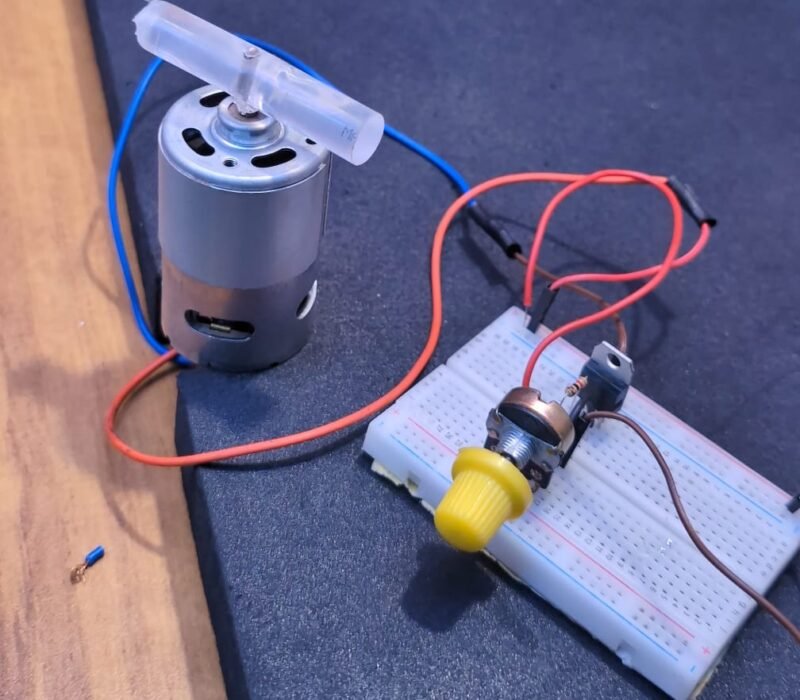
Hello guys, welcome back to Techatronic. Today we are making a tutorial on How to control DC motor speed using MOSFET TIP122. Every time whenever we talk about the motor speed control we assume a regulator which modulate the Pulse width. in result the speed of a DC motor can be control. In this Tutorial we will make a regulator using TIP122 MOSFET and 10k potentiometer. We have seen a lot of regulator in our daily life. we use regulator for fan , cooler , other machinery motor.

Although controlling of a dc motor is very easy we will increase the current to the gate terminal of the MOSFET and in result the current drawn from drain to source increase gradually. So, this is the working of this mosfet. The mosfet TIP 122 is widely used for controlling the brightness and dc motor speed.
To make this Project we need to know the Required components for the project.
Table of Contents
Required Components
- Breadboard
- TIP122
- DC motor 555
- 1k resistor
- Wires
- 12V power supply
So, in this Article, we will learn What is TIP 122 and how does it work. So, here we will use a 10k Potentiometer which will control DC motor speed.
TIP122

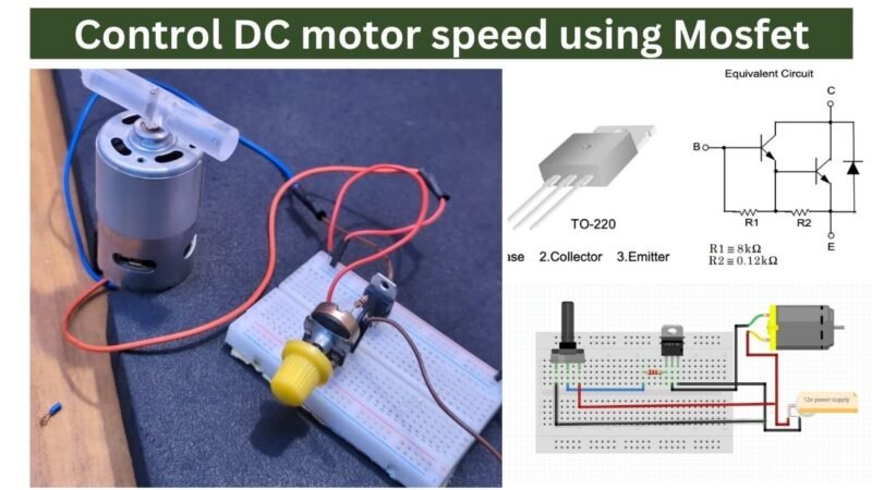
TIP122 is an NPN Epitaxial Darlington Transistor. Which is widely used in electronic circuits. The TIP 122 have 3 terminal gate, drain and source. Terminal 1 is gate , terminal 2 is drain, terminal 3 is source, Gate is to be connect to the potentiometer output pin and terminal 2 mean drain is to be connect to the load ground. terminal 3 is to be connect to the source which is 12v ground. and 12v positive.
Medium Power Linear Switching Applications
Complementary to TIP125 / TIP126 / TIP127
these are the two features of this transistor.
here we have shared the TIP122 datasheet.
Absolute Maximum Rating

If the maximum rating is exceeded the device may damage. the working of the transistor mosfet may differ due to the exceed range of voltage. extended exposure to stresses above the recommended operating conditions may affect device reliability.
DC motor 555
We are using 555 Dc Motor for this tutorial. it run on 12v. 555 motor have two terminal. both terminal can use for replace the direction. if we change the polarity the direction will be change automatically. So, Terminal 1 is to be connect to the positive wire of power supply and negative terminal is to be connect to the negative wire. but with the connection of TIP122 the negative wire of power source will be connect to the TIP122 of source pin and 555 motor terminal T1 is to be connect to the Drain pin of TIP122. Motor Terminal 2 is to be connect to the positive pin of power source to Control DC motor speed using Mosfet.
Dc motor having armeture which have 3 coil connected with the slip ring. and there is some permanent magnet inside the motor which make a magnetic field and when the current given to the armeture the coil get magnetise and make the magnetic field opposite to the direction of the permanent motor which cause the rotation to the armeture.
10k Potentiometer
We will use this potentiometer to give the power to the gate pin of TIP122. 10k potentiometer having 3 pins vcc, gound and output. so we will connect all these pins according to the circuit diagram. and when we rotate the potentiometer the voltage will be decrease or increase. this variability of voltage make changes into the output of the TIP122.
Control DC motor speed using Mosfet Circuit Diagram
The circuit diagram is very simple of this project. which is given as below.

Connect T1 of TIP122 to the potentiometer middle pin across the 1k resistor in series.
Connect T2 of TIP122 to the Motor negative pin
Connect T3 of TIP122 with the 12v power source ground pin
Connect motor positive pin to the positive pin of 12v power supply
Now remaining of two pin from the potentiometer will be connect to 12v power supply positive and negative pin.
Here all the connection have been done.
During the connection make sure the power should be turn off
Make sure all the connection should be right and tight.
Now you can use your circuit in Control DC motor speed using Mosfet. if you face any problem you can ask us in the comment section or visit our website.
Working on How to Control DC motor speed using Mosfet
When we connect the power source to our circuit the current start to flow from each of the closed loop. The mosfet which we are using is in open loop before we applying any voltage to te gate terminal. the connectivity between the drain and source is interrupted. we can assume this mosfet as a switch here. when we applied external force or external voltage then the current will start to floe from drain to source. and here we have motor which negative wire is connected with a switch with the mosfet drain and source.
so, whenever we rotate the potentiometer the voltage applied to the gate terminal will be increased which cause the connectivity between the drain and source and dc motor will be start gradually.
We can use this application in our many projects like
