
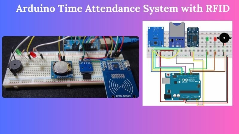
Hello guys, welcome back to Techatronic. Today we are going make an exciting project which is Arduino time attendance system with RFID. An RFID tag that is swiped in front of an RFID reader saves the user’s UID and time on an SD card. Additionally, it shows whether you are on schedule or running late, to the closest hour and minute.
This project is very suitable for Offices and schools. We need to have a record of our employees on when they come and when they leave the office. Before it was done by a human and it was very time consuming and had the possibility of errors. But with this project it can be done without human interference and accurate.
Table of Contents
Project Overview
- It has a reader for RFID tags that reads them;
- For timekeeping purposes, our setup includes a real-time clock module;
- An SD card is used to store the current time and the UID of an RFID tag that is read by the RFID reader.
- By using an SD card module, the Arduino can communicate with the SD card;
- One way to determine if they are late or on time is to set a check-in time.
- A red LED illuminates if you are running late, and a green LED illuminates when you are on time.
- Additionally, when a tag is read, the system’s buzzer beeps.
Components Required
| Arduino UNO | BUY LINK |
| MFRC522 RFID reader + tags | BUY LINK |
| Micro SD card | |
| SD card module | |
| SD1307 RTC module | BUY LINK |
| 2x LEDs (1x red + 1x green) | BUY LINK |
| 2x 220 Ohm resistor | BUY LINK |
| Breadboard | BUY LINK |
| Jumper Wires | BUY LINK |
MFRC522 RFID Reader
In this project we are using MFRC522 RFID Reader. Radio-frequency identification is known as RFID. RFID is useful for identifying individuals, completing transactions, and transferring data over short distances using electromagnetic fields.
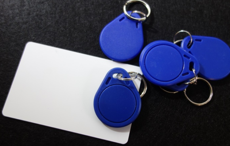
Tags: An electromagnetic card and a keychain are the two examples of items that have tags attached to them. RFID tags are also used by certain retailers to identify their products through their labels. A unique identification (UID) is assigned to each tag.
Reader: The user is dealing with a two-way radio apparatus that sends out a signal and deciphers the feedback from the tag.
This particular device is an MFRC522 RFID reader, operation at 3.3 volts, and it offers the possibility to communicate using SPI or I2C protocols. Since the library we’ll be employing for controlling the RFID reader is compatible only with SPI, we’ll be utilizing this communication method.
Specifications
- 13.56MHz RFID module
- Maximum Data Rate: 10Mbps
- Power down mode consumption: 10uA (min)
- Communication : SPI, I2C protocol, UART
- Read Range: 5cm
- Operating voltage: 2.5V to 3.3V
- Current Consumption: 13-26mA
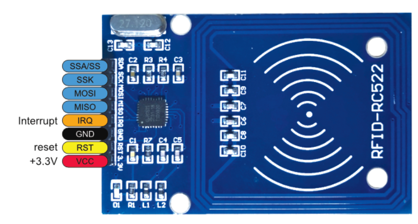
MFRC522 RFID Reader Pinout
MRFC522 RFID Reader connections to the Arduino board
| PIN | CONNECTION TO ARDUINO UNO |
| SDA | Digital 10 |
| SCK | Digital 13 |
| MOSI | Digital 11 |
| MISO | Digital 12 |
| IRQ | Don’t connect |
| GND | GND |
| RST | Digital 9 |
| 3.3V | 3.3V |
SD Card Module
Sometimes you have an idea for an Arduino project that requires a lot of log data storage along with additional functionality, such as a temperature or GPS logger. SD cards, also known as microSD cards, are another name for flash cards. Our lives would be impossible without them because of their ability to store gigabytes of data in a space smaller than a coin.
For the most part, microSD cards need an operating voltage of 3.0V. The microSD card may be permanently damaged by any voltage higher than 3.6V, so it can not be directly connected to circuits that use 5V logic. The module therefore includes an integrated ultra-low dropout voltage regulator that can adjust the voltage to within 3.3V.
SD Card Module Pinout
The SD Card is very simple to connect.
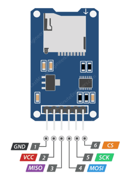
VCC pin gives power to the module and connects to the Arduino’s 5V pin.
GND is a ground pin.
MISO(Master In Slave Out) is the SPI output.
MOSID(Master Out Slave In) is the SPI input.
SCK(Serial Clock) this pin receives pulses from the master to synchronize data transmission.
SD Card Module connections to the Arduino Uno
| PIN | CONNECTIONS TO ARDUINO UNO |
| VCC | 3.3V |
| CS | Digital 4 |
| MOSI | Digital 11 |
| CLK | Digital 13 |
| MISO | Digital 12 |
| GND | GND |
RTC (Real Time Clock) Module
DS1307, a cheap, highly accurate RTC chip from Maxim, is the central component of the module. Through I2C, it connects to the microcontroller and manages all timekeeping tasks. Counting seconds, minutes, hours, days, dates, months, and years is possible with the DS1307.
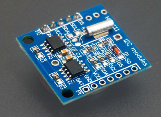
Along with an AM/PM indicator, it can operate in a 12 or 24 hour format. It automatically updates the date at the end of the month, taking leap year corrections into account, for months with fewer than thirty-one days.
The DS1307 IC has a battery input to guarantee accurate timekeeping even in the case of an interruption in the device’s main power supply. The integrated power-sense circuit continuously monitors the state of the VCC and automatically switches to the backup supply when a power outage occurs. This suggests that even in the event of a power outage, the IC can keep track of time.
RTC Module Pinout
| PIN | WIRING TO ARDUINO UNO |
| SCL | A5 |
| SDA | A4 |
| VCC | 5V (check your module datasheet) |
| GND | GND |
Installing RTCLib library
To install the RTCLib.h go to Sketch > Include Library > Manage libraries and search for RTCLib or follow these steps:
- The Download folder should contain a .zip folder.
- Get the RTCLib-master folder by unzipping the .zip folder.
- From RTCLib-master to RTCLib, rename your folder.
- To install the libraries for your Arduino IDE, move the RTCLib folder there.
- Open the Arduino IDE again at the end.
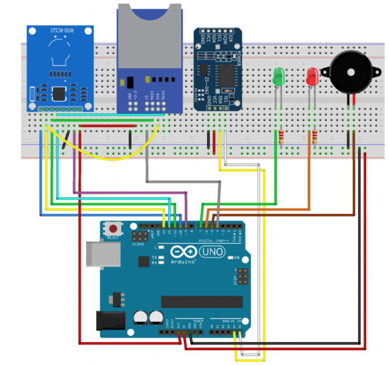
Circuit Diagram of Arduino Time Attendance System
The circuit connections of Arduino time attendance system is given below. In this circuit, some modules are for 3.3V and some are for 5V. Make connections carefully to avoid frying the module. If needed take a look at the connection tables give below.
Code of Arduino Time Attendance System
#include <MFRC522.h> // for the RFID
#include <SPI.h> // for the RFID and SD card module
#include <SD.h> // for the SD card
#include <RTClib.h> // for the RTC

// define pins for RFID
#define CS_RFID 10
#define RST_RFID 9
// define select pin for SD card module
#define CS_SD 4

// Create a file to store the data
File myFile;

// Instance of the class for RFID
MFRC522 rfid(CS_RFID, RST_RFID);

// Variable to hold the tag's UID
String uidString;

// Instance of the class for RTC
RTC_DS1307 rtc;

// Define check in time
const int checkInHour = 9;
const int checkInMinute = 5;

//Variable to hold user check in
int userCheckInHour;
int userCheckInMinute;

// Pins for LEDs and buzzer
const int redLED = 6;
const int greenLED = 7;
const int buzzer = 5;

void setup() {

  // Set LEDs and buzzer as outputs
  pinMode(redLED, OUTPUT);
  pinMode(greenLED, OUTPUT);
  pinMode(buzzer, OUTPUT);

  // Init Serial port
  Serial.begin(9600);
  while(!Serial); // for Leonardo/Micro/Zero

  // Init SPI bus
  SPI.begin();
  // Init MFRC522
  rfid.PCD_Init();

  // Setup for the SD card
  Serial.print("Initializing SD card...");
  if(!SD.begin(CS_SD)) {
    Serial.println("initialization failed!");
    return;
  }
  Serial.println("initialization done.");

  // Setup for the RTC
  if(!rtc.begin()) {
    Serial.println("Couldn't find RTC");
    while(1);
  }
  else {
    // following line sets the RTC to the date & time this sketch was compiled
    rtc.adjust(DateTime(F(__DATE__), F(__TIME__)));
  }
  if(!rtc.isrunning()) {
    Serial.println("RTC is NOT running!");
  }
}

void loop() {
  //look for new cards
  if(rfid.PICC_IsNewCardPresent()) {
    readRFID();
    logCard();
    verifyCheckIn();
  }
  delay(10);
}

void readRFID() {
  rfid.PICC_ReadCardSerial();
  Serial.print("Tag UID: ");
  uidString = String(rfid.uid.uidByte[0]) + " " + String(rfid.uid.uidByte[1]) + " " +
    String(rfid.uid.uidByte[2]) + " " + String(rfid.uid.uidByte[3]);
  Serial.println(uidString);

  // Sound the buzzer when a card is read
  tone(buzzer, 2000);
  delay(100);
  noTone(buzzer);

  delay(100);
}

void logCard() {
  // Enables SD card chip select pin
  digitalWrite(CS_SD,LOW);

  // Open file
  myFile=SD.open("DATA.txt", FILE_WRITE);

  // If the file opened ok, write to it
  if (myFile) {
    Serial.println("File opened ok");
    myFile.print(uidString);
    myFile.print(", ");

    // Save time on SD card
    DateTime now = rtc.now();
    myFile.print(now.year(), DEC);
    myFile.print('/');
    myFile.print(now.month(), DEC);
    myFile.print('/');
    myFile.print(now.day(), DEC);
    myFile.print(',');
    myFile.print(now.hour(), DEC);
    myFile.print(':');
    myFile.println(now.minute(), DEC);

    // Print time on Serial monitor
    Serial.print(now.year(), DEC);
    Serial.print('/');
    Serial.print(now.month(), DEC);
    Serial.print('/');
    Serial.print(now.day(), DEC);
    Serial.print(' ');
    Serial.print(now.hour(), DEC);
    Serial.print(':');
    Serial.println(now.minute(), DEC);
    Serial.println("sucessfully written on SD card");
    myFile.close();

    // Save check in time;
    userCheckInHour = now.hour();
    userCheckInMinute = now.minute();
  }
  else {
    Serial.println("error opening data.txt");
  }
  // Disables SD card chip select pin
  digitalWrite(CS_SD,HIGH);
}

void verifyCheckIn(){
  if((userCheckInHour < checkInHour)||((userCheckInHour==checkInHour) && (userCheckInMinute <= checkInMinute))){
    digitalWrite(greenLED, HIGH);
    delay(2000);
    digitalWrite(greenLED,LOW);
    Serial.println("You're welcome!");
  }
  else{
    digitalWrite(redLED, HIGH);
    delay(2000);
    digitalWrite(redLED,LOW);
    Serial.println("You are late...");
  }
}
Click here for more Arduino projects.
FAQ(Frequently Asked Questions) for Arduino Time Attendance System
Q.1 Why my code is not working?
Ans. Check your wiring connections first. Many times people do wrong wiring. Check, you have installed the right libraries and included those in your code.
Q.2) How to download the required libraries?
Ans. Open Arduino IDE and click on sketch > click include libraries > click Manage libraries. Search RTCLib and download that.