Digital Dice Using 4017 IC And 555 IC | 555 Timer project
Table of Contents
Introduction
Hey techies, we are back with another new post in the series of 555 ic projects. We are sure that you know what dice are and their uses. Well if so then in this article we are going to make a digital dice 555 timer project with the help of 4017 ic and 555 timer ic.

Dice is a cubical object with numbers printed on each face. It has six faces and numbers from 1 to 6. We can use it for playing many indoor games like ludo etc. You can also check out our articles on Arduino and IoT.
Make the connections according to the circuit diagram which is given below.
555 timer project Description
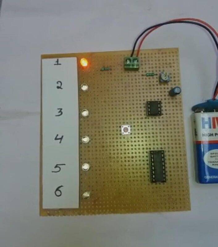
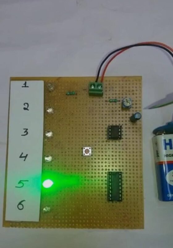
- For rolling the dice you just have to press the pushbutton.
- The LEDs will start glowing which looks like flashing lights and a random LED will remain on, others will turn off.
- In this way, you can get a random number just like a physical dice.
- You can also check the square wave generator using 555 ic made by us.

Components Required
- 4017 ic
- 555 timer ic
- Pushbutton
- 1N4148 Zener diode
- LEDs
- Resistors 10K, 1M, 220 ohm, 1K
- Capacitors 1000 uF, 0.01 uF, 1 uF, 0.22 uF
- 9 volts battery
- Connecting wires and a breadboard
Circuit 555 ic timer ic project
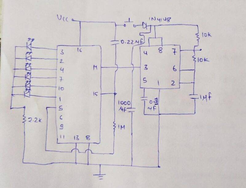
- Take a 555 timer ic and join its pin number 1 with the negative rail of the breadboard and pin number 8 with a pin of the pushbutton.
- Connect pin 4 and pin 8 together. Attach pin 3 (output pin of the 555 timer ic) with pin number 14 of the 4017 ic.
- Now connect the negative leg of a 1 uF capacitor with the negative rail and the positive leg with pin 2 of the ic.
- Place a 0.01 uF capacitor between pin 5 and the negative rail.
- Join pins 2 and 6 together. Connect pins 6 and 7 together via a 10K resistor.
- Place a 10K resistor between pin 7 and the positive rail.
- You have to take a pushbutton and connect one set of interconnected pins with the positive supply and the other pair of interconnected pins with the 555 timer pins using a Zener diode as shown in the figure.
- Now let us see the connections for the 4017 ic. Join pin 16 of the ic with the positive supply.
- Connect pins 8 and 13 with the negative rail. Attach a 1M resistor between pins 5 and 15.
- Place a 0.22 uF capacitor between pin 15 and the positive rail. Take a 1000 uF capacitor and connect its positive leg with the pin of the pushbutton and negative leg with the negative rail as shown.
- Join the positive terminal of LED 1 with pin 3, LED 2 with pin 2, LED 3 with pin 4, LED 4 with pin 7, LED 5 with pin10, LED 6 with pin 1 of the 4017 IC.
- Connect the negative terminals of these LEDs with the negative rail via a 220 ohm resistor. Your circuit is now ready for testing.
Let us Test the Circuit
We hope that you like this project of digital dice and now try to make it on your own. If you have any doubts regarding this post then feel free to use the comments section given below. Also, do check out more projects on Arduino and Raspberry Pi.

Thanks for reading.
latest 555 timer projects
Railway Signal Using 555 Timer IC | 555 IC project
Monostable Multivibrator using 555 timer | 555 Monostable Multivibrator
555 delay timer with ON/OFF | 555 timer delay off circuit